Dev Kit Manual 53 323094
4.6 Other Headers
4.6.1 H8 Programming Header
The microcontroller firmware for system management/keyboard/mouse control can be
upgraded in two ways. The user can either use a special DOS* utility (in-circuit) or use an
external computer connected (remote) to the system via the serial port on the board.
If the user chooses to use an external computer connected to the system via the serial port,
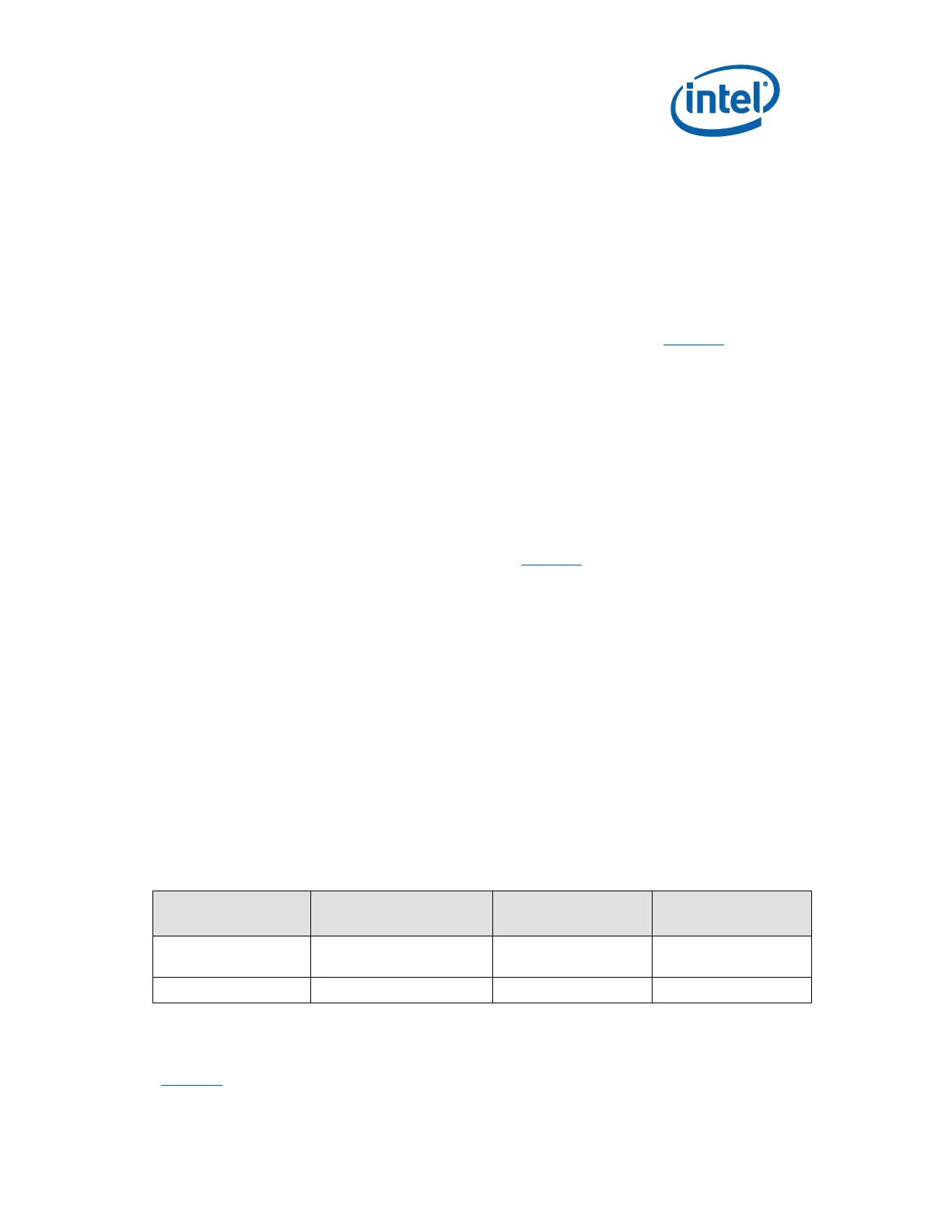
there are four jumpers that must be set correctly first. Please refer to Table 12 for a summary
of these jumpers.
Required Hardware: One Null Modem Cable and a Host Unit with a serial COM port (System
used to flash the SUT)
Here is the sequence of events necessary to program the H8:
1. Extract all files (keep them in the same folder) to a single directory of your choice on
the host machine or on a floppy disk (recommended).
2. Connect a NULL modem cable to the serial ports of each platform (host and unit to be
flashed).
3. Boot host in DOS mode.
4. Set the jumpers on the motherboard as in Table 22.
5. Power on the motherboard and press the PWR button.
6. From the host directory where you extracted the files, run the following command
line:
KSCFLAxx ksc.bin / Remote
xx refers to the KSC flash utility version number.
Note: This file will program ksc.bin to the KSC flash memory through the remote (Null modem
cable).
7. Follow the instructions that the flash utility provides.
8. After successful programming of the KSC, switch-off motherboard power and move all
three jumpers back to their default setting. The program assumes the host computer
is using serial port 1.
Note: Make sure the board is not powered on, and the power supply is disconnected before moving
any of the jumpers.
Table 22. H8 Programming jumpers
Short pin 2 and 3
(Default: 1-2)
Short pin 2 and 3
(Default: 1-2)
4.6.2 Expansion Slots and Sockets
Table 23 is a list of the slots and sockets available for attaching additional devices.