38 323094 Dev Kit Manual
3.7.3.3 Power Supply Solution
The motherboard contains all of the voltage regulators necessary to power the system up.
Note: Use an “ATX12V” 1.1 Spec compliant power supply (an "ATX12V" rating means V5 min current
=0.1 A, "ATX" V5 min current = 1.0 A, among other differences).
Note: If the power button on the ATX power supply is used to shut down the system, wait at least
five seconds before turning the system on again. We do not recommend shutting down the
system this way.
3.7.4 Debugging Interfaces
3.7.4.1 Processor Debug
An XDP (Extended Debug Port) connector is provided at J1D3 for processor run control debug
support.
A port 80-83 display add-in card can also be used for debug. The port 80-83 add in card could
be used on the TPM header located at J9A1.
3.7.4.2 Chipset Debug
An XDP Connector is provided at J8H3, for chipset debug support.
3.7.5 Power Management
3.7.5.1 Power Management States
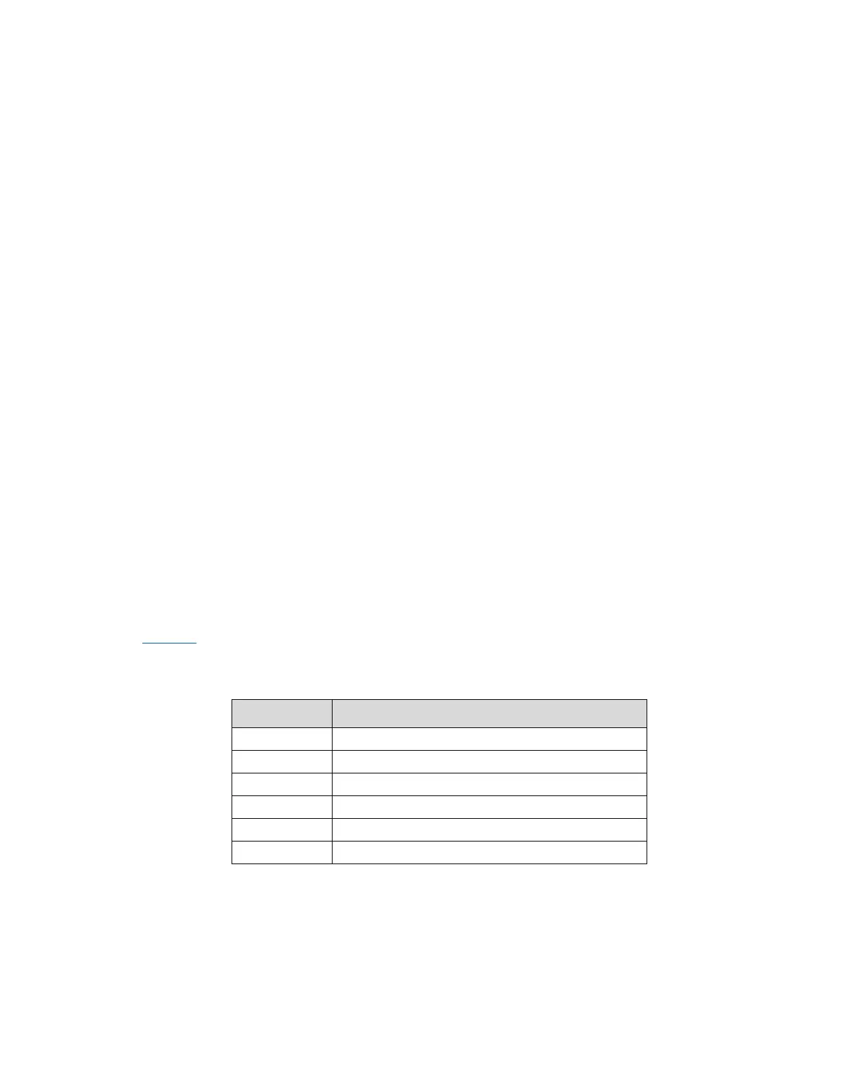
Table 13 lists the power management states. The Controller Link (CL) operates at various
power level, called M-states. M0 is the highest power state, followed by M3 and M-off.
Table 13. Power Management States
Deep Sleep: CPUSTP# signal active
Suspend To RAM (all switched rails are turned off)
3.7.6 Power Measurement Support
Power measurement resistors are provided on the platform to measure the power of most
subsystems. All power measurement resistors have a tolerance of 1%. The value of these