41 Controlling a PE650 Receiver
Chapter 11:
Controlling a PE650 Receiver
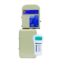
If you are installing a MultiWave to a system that includes a PE650 Receiver, follow the
procedure below to link the PE953 Hand-Held Controller with the PE650 Receiver.
/LQNLQJWKH3(&RQWUROOHUZLWK3(5HFHLYHU
This procedure creates a network between the Hand-Held Controller and the PE650 Receiver,
making it possible to complete the rest of the setup procedure and operate the system.
1. Press and release any button to activate the controller.
2. Press P/S and ENTER simultaneously to access LEARN MODE.
3. Press the 3 function button to select INCLUDE DEVICE. The screen
refreshes with instructions to PRESS BUTTON ON DEVICE TO
INCLUDE, as shown.
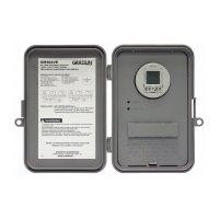
4. Press the BLACK BUTTON on the base of the antenna of the PE650.
The screen displays the word SUCCESSFUL, as shown, then returns
to the LEARN MODE screen.
NOTE: If the two devices are not successfully linked and you are seeing the
word FAILURE at the bottom of the screen, carefully repeat the procedure. If
the problem persists, contact Intermatic Customer Service.
5. Press the ENTER button if you wish to return to the main display screen.
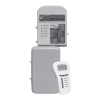
6. The circuits wired in the PE650 network (up to ve) can now be controlled
ON/OFF with the ve function buttons on the PE953 Hand-Held
Controller.
&RQWUROOLQJ3()XQFWLRQV
Depending on how the site has been installed with the PE650 Receiving Device, there may be up
to ve circuits being controlled. The ve function buttons on the PE653 Hand-Held Controller will
control the ve circuits in the PE650 Receiving Device.
1. Press any button to activate the controller.
2. If the PE650 screen (shown at the right) is not displayed, press the
ENTER button until you see the PE650 screen, as shown.
3. Press the function button for the circuit that you want to turn ON or
OFF.
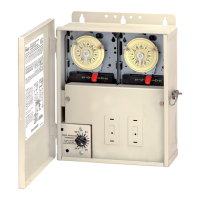
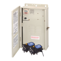
• Buttons 1, 2, and 3 control circuits 1, 2, and 3 on the Three-Circuit Clock Mechanism
(P1353ME) that is installed on the left side of the Receiving Device.
• Buttons 4 and 5 control Relay 1 and Relay 2 on the Valve/Pump Switch Control
(P4243ME) that is installed on the right side of the Receiving Device.
NOTE: The controller’s display shows the circuit number along the top of the screen.
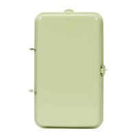
Figure 11-1. PE650 Receiver.