142 Intermec EasyCoder PF2i, PF4i, and PF4i Compact Industrial—Service Manual
Chapter 13—CPU Board
13.1 Description
The CPU board is a four-layer board with most of its circuits surface-
mounted. Inside the laminate are a combined VCC layer (5V/3.3V/2.5V)
and a GND layer. The front and back sides are signal routing layers.
The hardware contains of the following main functions:
• Processor core
• Thermal printhead driver
• Stepper motor control logic
• Sensor drivers
• Communication, such as UART, USB, etc.
• Flash memory SIMM for the fi rmware and non-volatile storage
• SDRAM SIMM for working memory
• A/D converter for sensor adjustment, etc.
• Compact Flash memory card expansion
• Expansion bus
• PCI bus (custom)
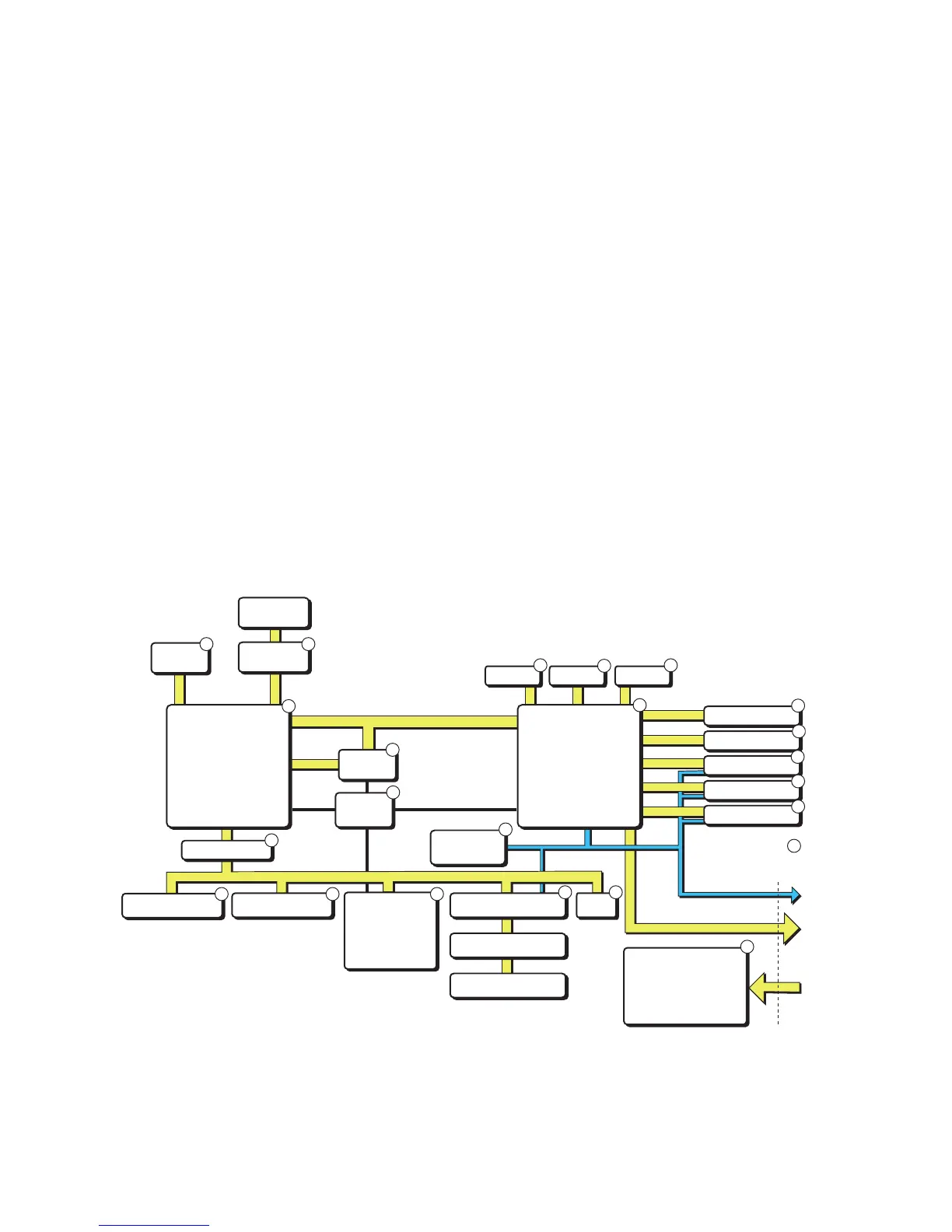
1-971630-25 CPU board; Block Diagram
(numbers refer to schematics in Chapter 13.7)
I
2
C bus
Power conversion
5V
3.3V
2.5V
24V In
Stepper control signals
(only one optional
board in PF-series)
PSU/Motor
interface
Sensors
A/D converter
TPH
Console
Finisher
Clock
48 MHz
CLIC
Support logic
Board id
Reset
Exp. interface
Optional board
(Optional board)
Flash memory
Compact Flash
USB
UART
PCI bus
(custom)
Network
card
Beeper
iButtonWand
CPU
RISC core
Memory controller
PCI interface
PSA
TPH logic
Stepper logic
Interrupt
I
2
C master
Bus isolation
CPU board
EEPROM
1
1
2
2 2 2
3
3
3
4
5
5
5
5 5
5
5
6 6
6
7
8
SDRAM
1