176 Intermec EasyCoder PF2i, PF4i, and PF4i Compact Industrial—Service Manual
Chapter 14—Interfaces
Digital Opto Out
The current to each optocoupler of the digital OUT ports 221-228 can be
turned on and off using PORTOUT ON/OFF statements.
The status of the ports can be read using PORTIN functions. If a current
is led through the optocoupler of the port, PORTIN returns the value -1
(true), else it returns the value 0 (false).
Signal Description Max.
Vceo Collector-Emitter breakdown voltage 35V
Veco Emitter-Collector breakdown voltage 6V
Collector Current 15 mA
Vog Output to ground (optocoupler) 100V
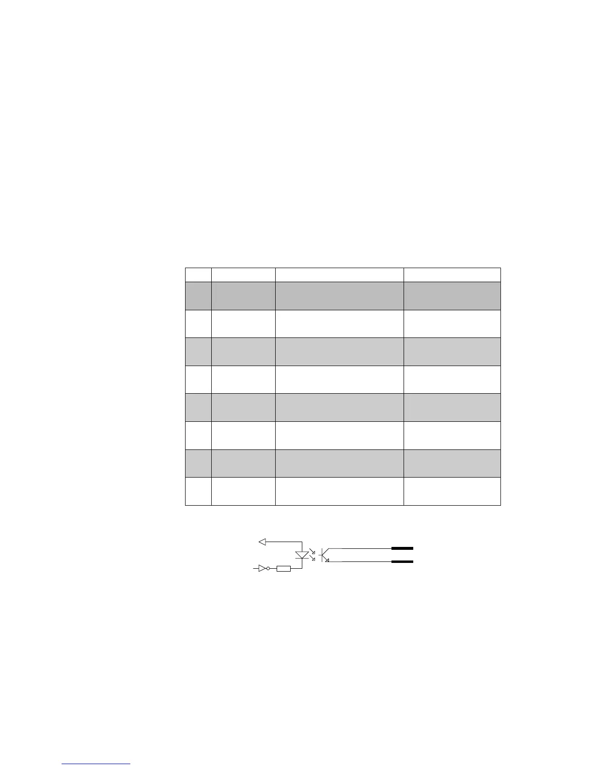
Connector Configuration
Simplifi ed schematics of a digital OUT port.
VCC
OUTa
OUTc
Pin Signal Name Description Fingerprint Ref. No.
20 Out1c Collector Opto Out Channel 1 221
5 Out1e Emitter Opto Out Channel 1
35 Out2c Collector Opto Out Channel 2 222
21 Out2e Emitter Opto Out Channel 2
6 Out3c Collector Opto Out Channel 3 223
36 Out3e Emitter Opto Out Channel 3
22 Out4c Collector Opto Out Channel 4 224
7 Out4e Emitter Opto Out Channel 4
37 Out5c Collector Opto Out Channel 5 225
23 Out5e Emitter Opto Out Channel 5
8 Out6c Collector Opto Out Channel 6 226
38 Out6e Emitter Opto Out Channel 6
24 Out7c Collector Opto Out Channel 7 227
9 Out7e Emitter Opto Out Channel 7
39 Out8c Collector Opto Out Channel 8 228
25 Out8e Emitter Opto Out Channel 8