Assembly and installation
Version 3.0 (08/2018)
20 Translation of original instruction manual
5.4 Electrical installation
Connecting the power supply
The power supplies use two 3G3G-FL flat cables with a core cross-section of 2 x 2.5 mm
2
.
By using two flat cables, the RollerDrive and the sensors / logic are powered separately. This
enables safe switching off of the RollerDrive without losing the bus communication.
To use the MultiControl as a spare part in existing systems, a FK distributor can be
used (see "Accessories").
The two ground potentials (L-) of the power supplies are interconnected in the MultiControl.
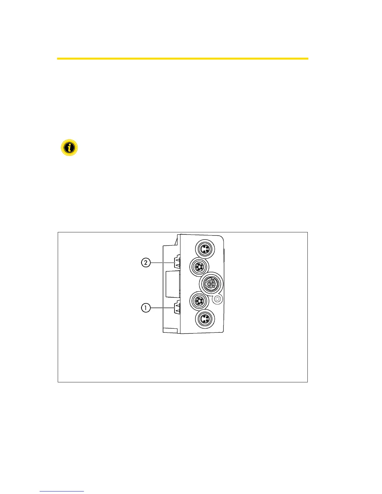
➢ Insert the flat cables in the correct orientation without tension or torsion into the cable
guides of the base plate. The cable guides are form-fitting (see illustration). As a result, the
flat cables can only be inserted in one orientation and the cables cannot be reversed.
➢ If necessary, take measures for strain relief or vibration reduction.
Cable duct for logic and sensor
voltage supply (L1)
Cable duct for RollerDrive voltage
supply (L2)
Pin at top: L+, brown core of line
Pin at top: L+, brown core of line
Pin at bottom: L-, blue core of line
Pin at bottom: L-, blue core of line