Assembly and installation
Version 3.0 (08/2018)
Translation of original instruction manual 21
➢ Seal the ends of the flat cables with end caps to achieve IP54 protection.
➢ Mount the MultiControl on the base frame to establish the correct contact bonding (see
„Initial assembly“, page 16).
➢ Connect cables to the voltage source. Connect the brown wire to L + and the blue wire to
L-.
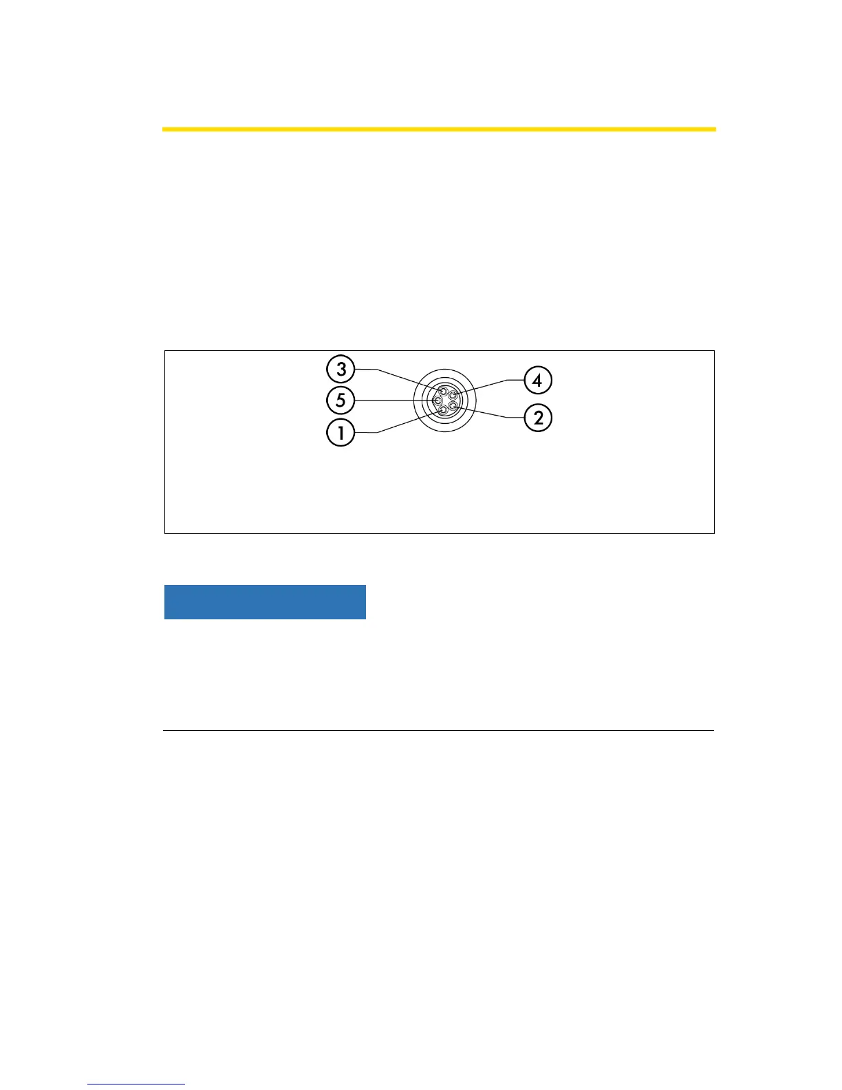
Connecting the RollerDrive
The four connections "RD1" to "RD4" are prepared for the Interroll RollerDrive.
Connections are not short-circuit proof
In the event of a short circuit, in particular between pin 1 and pin 3, the internal fuse
(PTC) in the MultiControl triggers. Normal operation is possible again after the internal
fuse has cooled down.
➢ Ensure correct polarity.