EasyManuals Logo

Interroll MultiControl Instruction Manual

Interroll MultiControl
66 pages
To Next Page IconTo Next Page
To Previous Page IconTo Previous Page
Page #29 background imageLoading...
Page #29 background image
Assembly and installation
Version 3.0 (08/2018)
Translation of original instruction manual 23
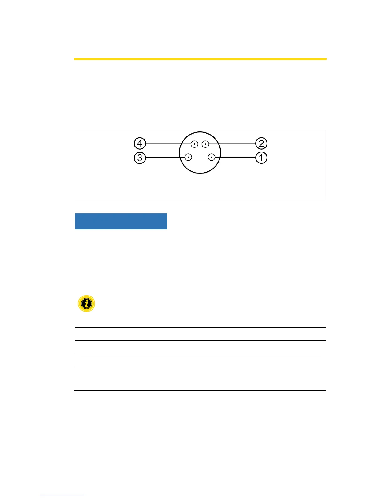
Connecting the sensors
Four sensors and four additional inputs or outputs (AUX I / O) can be connected to the "Sensor
1, I / O 1" to "Sensor 4, I / O 4" connections. PNP or NPN sensors as well as sensors with NC or
NO contact can be used. The sensor type and the function of the additional I/O can be
parameterized (see "Digital I/O Settings", page 32). Using a Y-line, a sensor and an input/output
can be connected to one connection at the same time (see Accessories“, page 57).
1
+24 V
3
Ground
2
AUX I/O
4
Sensor input
NOTICE
Connections are not short-circuit proof
In the event of a short circuit, in particular between pin 1 and pin 3, the internal fuse
(PTC) in the MultiControl triggers. Normal operation is possible again after the internal
fuse has cooled down.
Ensure correct polarity.
The inputs and outputs are not electrically isolated.
Characteristic values for the inputs
Input voltage
0 V to 24 V DC
Input resistance
≥ 15 kΩ
Switching thresholds
≥ 15 V „High“
≤ 5 V „Low“

Table of Contents

Other manuals for Interroll MultiControl

Questions and Answers:

Question and Answer IconNeed help?

Do you have a question about the Interroll MultiControl and is the answer not in the manual?

Interroll MultiControl Specifications

General IconGeneral
Power Supply24 VDC
Rated Voltage24 VDC
Storage Temperature-20 °C to +70 °C
Communication ProtocolsEthernet/IP, PROFINET, EtherCAT, CANOpen
Number of Channels4
Weight0.5 kg

Related product manuals