Goodrive35 inverters Basic operation instruction
237
B -
B +
A -
A +
+5V
使用屏蔽线
B
A
+5V
OV
B
A
0 V
VCC
PE
PWR/+24V
COM1/COM
Z -
Z +
+5V
Z
Z
推
拉
式
输
出
编
码
器
OV
OV
Vcc
B -
B +
A -
A +
+5V
使用屏蔽线
B
A
+5V
OV
B
A
0 V
VCC
PE
PWR/+24V
COM1/COM
Z -
Z +
+5V
Z
Z
OV
OV
推
拉
式
输
出
编
码
器
Vcc
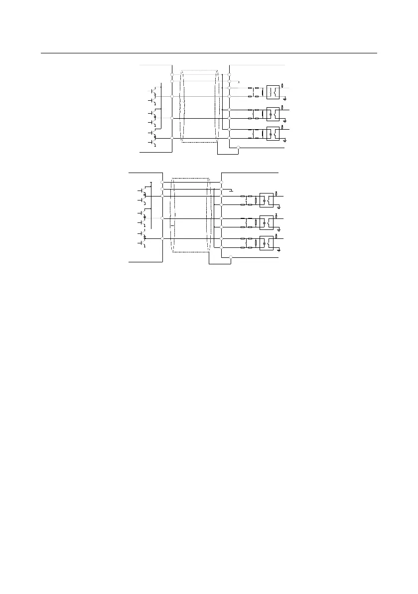
Mode 1 Mode
2
Note: when this output mode is used, please refer to the electrical specifications in the encoder
manual.
①. If the flowing-out current of the output current is less than 25mA and the flowing–in current is
more than 25mA, please apply mode 1
②. If the flowing-in current of the output current is less than 25mA and the flowing –out current is
more than 25mA, please apply mode 2
③. If the flowing-in and flowing –out current of the output current is more than 25mA, please apply
mode 1 or 2.
4. Note: Z signal is needed for the spindle positioning inverter and the wiring is the same as
that of A and B signal.
7.16.2 Commissioning steps
1. Close loop vector debugging of AM
(1) Set P00.18=1 and restore to the factory settings.
(2) Set the parameters of P00.03, P00.04 and P02 group
(3) Motor autotuning
a) Set P00.15=1 and begin rotating autotuning

 Loading...


