Goodrive35 inverters Installation guidelines
33
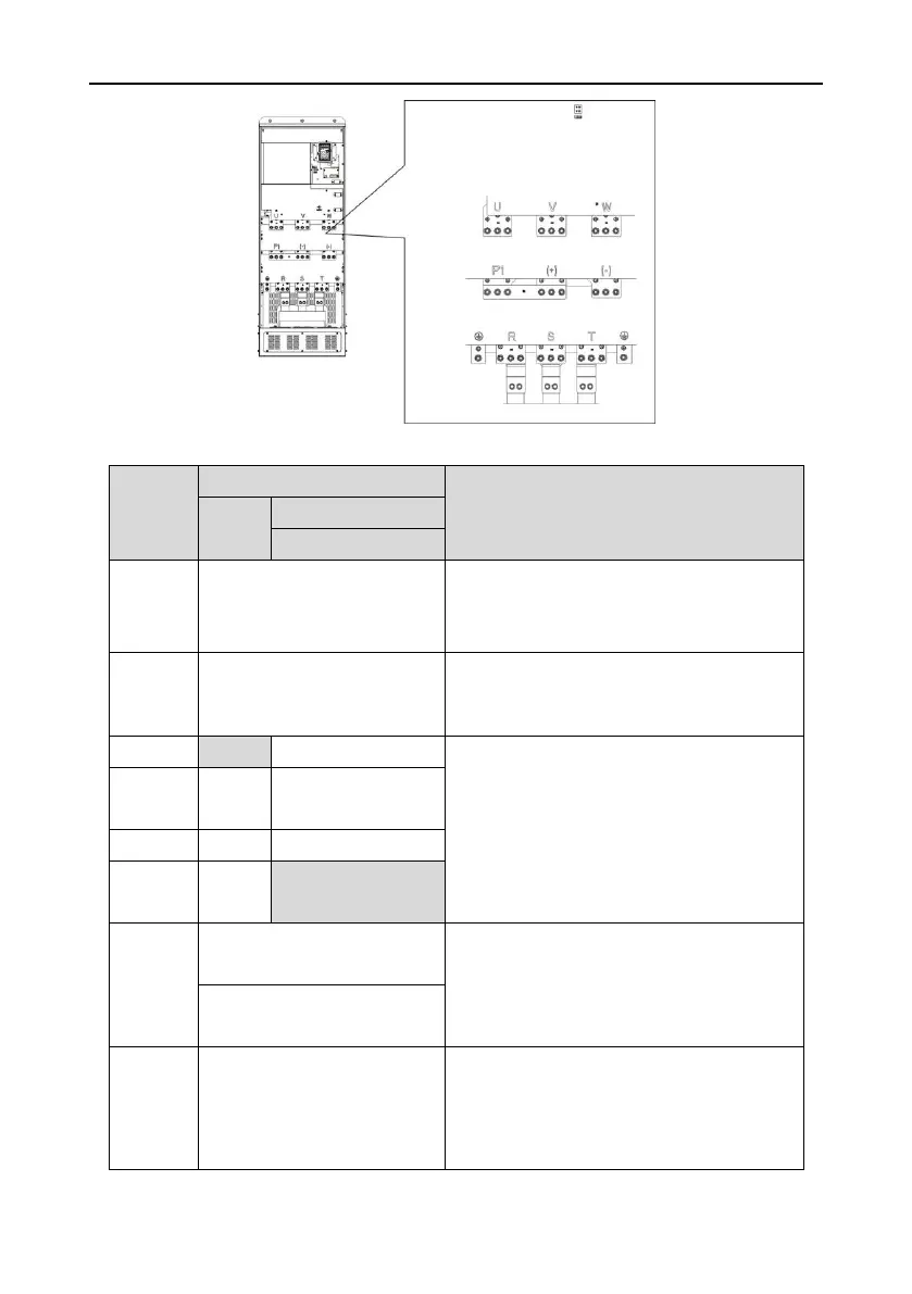
Fig 4-18Terminals of main circuit for the inverters of 660V 400~630kW
Power input of the main circuit
3-phase AC input terminals which are generally
connected with the power supply.
3-phase AC output terminals which are generally
connected with the motor.
P1 and (+) are connected with the terminals of
DC reactor.
(+) and (-) are connected with the terminals of
braking unit.
PB and (+) are connected with the terminals of
braking resistor.
DC reactor terminal 2,
braking unit terminal 1
380V: the grounding resistor is
less than 10Ohm
Protective grounding terminals, every machine is
provided 2 PE terminals as the standard
configuration. These terminals should be
grounded with proper techniques.
660V: the grounding resistor is
less than 10Ohm
Control power supply terminal
Optional for the inverters of 380V, standard for
the inverters of 660V(with external 220V control
power supply)
If no voltage is present on the main circuit, more

 Loading...


