Goodrive35 inverters Installation guidelines
37
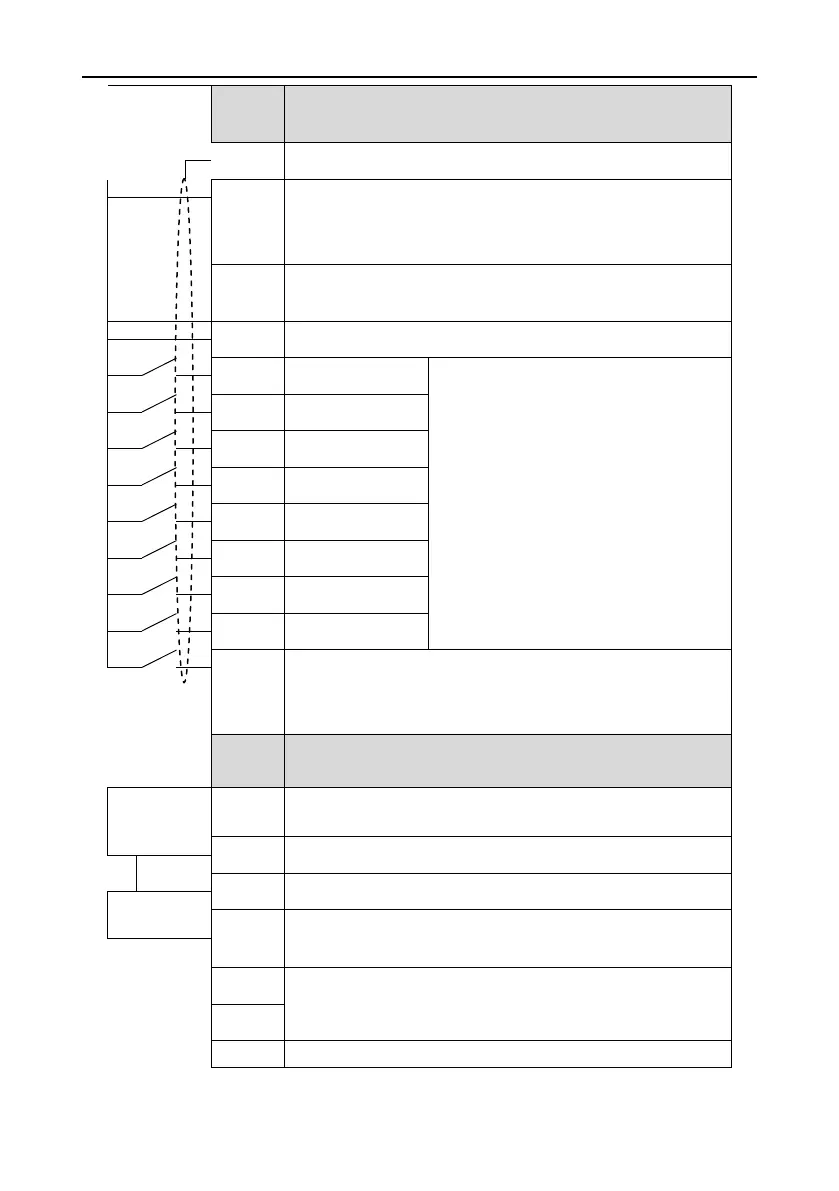
Provide the input switch working power supply from external to
internal.
Voltage range: 12~24V
The inverter provides the power supply for users with a maximum
output current of 200mA
1. Internal impedance:3.3kΩ
2. 12~30V voltage input is available
3. The terminal is the dual-direction input
terminal supporting both NPN and PNP
4. Max input frequency:1kHz
5. All are programmable digital input
terminal. User can set the terminal function
through function codes.
Except for S1~S8, this terminal can be used as high frequency
input channel.
Max. input frequency:50kHz
1. Switch input: 200mA/30V
2. Output frequency range: 0~50kHz
Common terminal of the open collector pole output
1.Swtich capability: 200mA/30V
2.Output frequency range: 0~1kHz
485 communication interface and 485 differential signal interface
If it is the standard 485 communication interface, please use
twisted pairs or shield cable.

 Loading...


