EasyManuals Logo

INVT Goodrive 35 Series User Manual

INVT Goodrive 35 Series
344 pages
To Next Page IconTo Next Page
To Previous Page IconTo Previous Page
Page #39 background imageLoading...
Page #39 background image
Goodrive35 inverters Installation guidelines
38
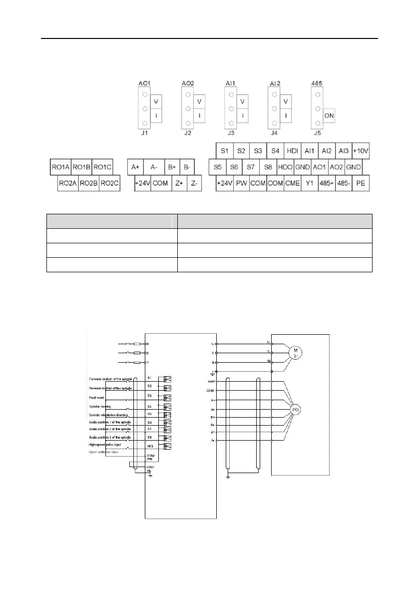
4.4.2 C1 terminal (EC-PG301-24) and the wiring diagram
4.4.2.1 Terminal arrangement
4.4.2.2 The terminal
Terminal
Instruction
+24V
Power supply, provide 24V, 200mA power supply
A+, A-, B+, B-, Z+, Z-
Signal input
COM1
Grounding terminal of the encoder
Note: refer to section 4.4.1 for detailed information of AO1, AO2, AI1, AI2, 485 and other
terminals.
4.4.2.3 The wiring diagram
www.barghmaher.ir

Table of Contents

Questions and Answers:

Question and Answer IconNeed help?

Do you have a question about the INVT Goodrive 35 Series and is the answer not in the manual?

INVT Goodrive 35 Series Specifications

General IconGeneral
BrandINVT
ModelGoodrive 35 Series
CategoryInverter
LanguageEnglish

Related product manuals