Goodrive35 inverters Installation guidelines
40
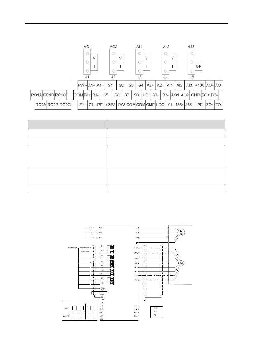
4.4.4 H1 terminal (EC-PG305-12) and the wiring diagram
4.4.4.1 Terminal arrangement
4.4.4.2 The terminal
Power supply, provide 5V/12V, 200mA power supply
A1+, A1-, B1+, B1-, Z1+, Z1-
Pulse reference signal, default as 5V input. External
current-limiting resistor is needed when the input
voltage is above 10V
AO+, AO-, BO+, BO-, ZO+ and ZO-
Encoder signal output, 5V differential signal and the
ratio of frequency-division is 1:1
Grounding terminal of the encoder
Note: refer to section 4.4.1 for detailed information of AO1, AO2, AI1, AI2, 485 and other
terminals.
4.4.4.3 The wiring diagram

 Loading...


