Goodrive270 series VFD for fan and pump Basic operation guidelines
-138-
This figure assumes that the VFD outputs and controls motor M2, M1 is in power-frequency run mode,
and M3–M4 are in the stopped state. At this time, if the VFD output frequency is equal to or lower than
P94.25 (Running frequency for motor reducing), PID1 feedback is less than the difference between
PID1 reference and P94.24 (Pressure tolerance for motor reducing), and this condition lasts a period
of time longer than P94.26 (Motor reducing delay), the motor reducing function is triggered. There are
two motor reducing actions for selection, which can be set by P94.27 (Variable-frequency motor
action for motor reducing).
When P94.27=1
The VFD improves the output frequency to P94.20 (Running frequency for motor adding) within the
time specified by P94.28 (ACC time for motor reducing). When the ACC is completed, the VFD
disconnects the relays corresponding to the motors in power-frequency run mode.
When P94.27=0
The VFD directly disconnects motor M1 in power-frequency run mode, and adjusts the frequency of
motors in variable-frequency run mode through PID to reach the given water pressure.
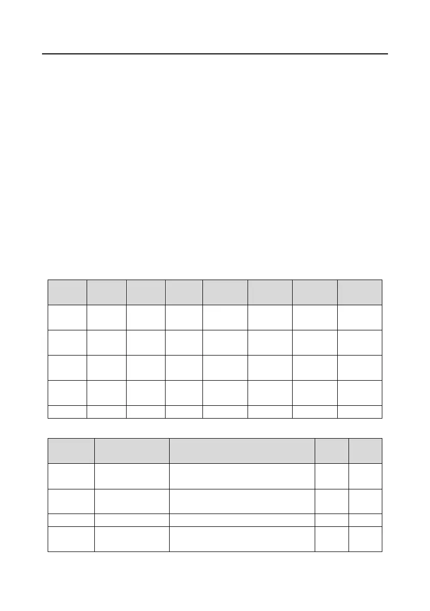
The following table lists the relay action logic in the motor reducing process.
Table 5-4 Motor reducing logic in circular variable-frequency run mode
Related function codes:
Pressure tolerance
for motor adding
0.0–30.0% (relative to PID1 max. value)
Running frequency
for motor adding
P94.25 (Running frequency for motor
reducing)–P00.03
P00.05 (Lower limit frequency)–P00.03
 Loading...