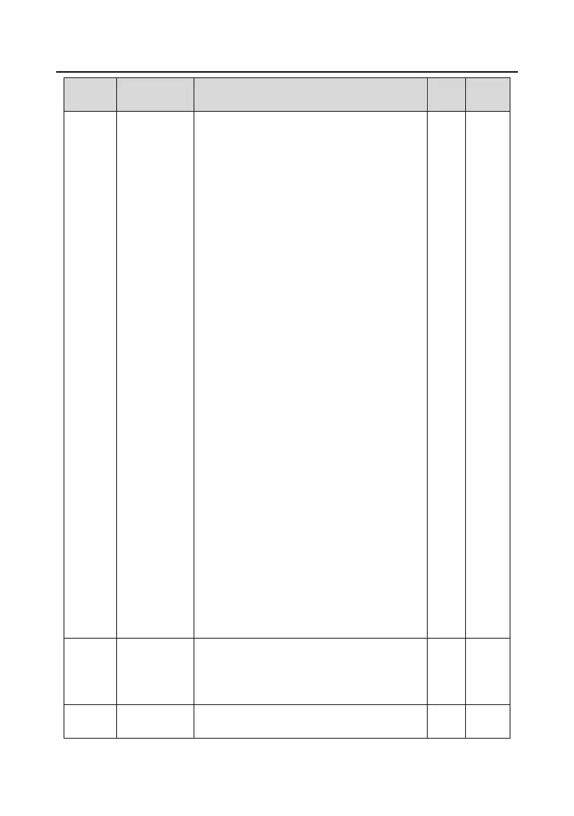
75: Pause PID2 integral
76: Pause PID2 control
77: Switch PID2 polarities
78: Disable HVAC (only in stopped state)
79: Trigger fire signal
80: Pause PID1 control
81: Pause PID1 integral
82: Switch PID1 polarities
83: Trigger sleep mode
84: Trigger wakeup mode
85: Manual polling
86: Pump cleaning signal
87: Water level upper limit of inlet pool
88: Water level lower limit of inlet pool
89: Water shortage level of inlet pool
90–95: Reserved
96: Manual soft startup for motor A
97: Manual soft startup for motor B
98: Manual soft startup for motor C
99: Manual soft startup for motor D
100: Manual soft startup for motor E
101: Manual soft startup for motor F
102: Manual soft startup for motor G
103: Manual soft startup for motor H
104: Disable motor A
105: Disable motor B
106: Disable motor C
107: Disable motor D
108: Disable motor E
109: Disable motor F
110: Disable motor G
111: Disable motor H
Used to set the polarity of input terminals.
When a bit is 0, the input terminal is positive;
when a bit is 1, the input terminal is negative.
0x00–0x3F

 Loading...