EasyManua.ls Logo

INVT Goodrive270 Series - Page 194

INVT Goodrive270 Series
372 pages
To Next Page IconTo Next Page
To Previous Page IconTo Previous Page
Loading...
Goodrive270 series VFD for fan and pump Function parameter list
-184-
Function
code
Name
Description
Default
Modify
Sin
FWD
REV
Running
direction
ON
OFF→ON
ON
FWD run
OFF
FWD run
ON
ON
OFF→ON
REV run
OFF
REV run
ON→OFF
Decelerate
to stop
Sin: Three-wire control; FWD: Forward running;
REV: Reverse running
Note: For two-wire controlled running mode, when
the FWD/REV terminal is valid, if the VFD stops
due to a stop command given by another source,
the VFD does not run again after the stop
command disappears even if the control terminal
FWD/REV is still valid. To make the VFD run, you
need to trigger FWD/REV again, for example, PLC
single-cycle stop, fixed-length stop, and valid
STOP/RST stop during terminal control. (See
P07.04.)
P05.12
S1 switch-on
delay
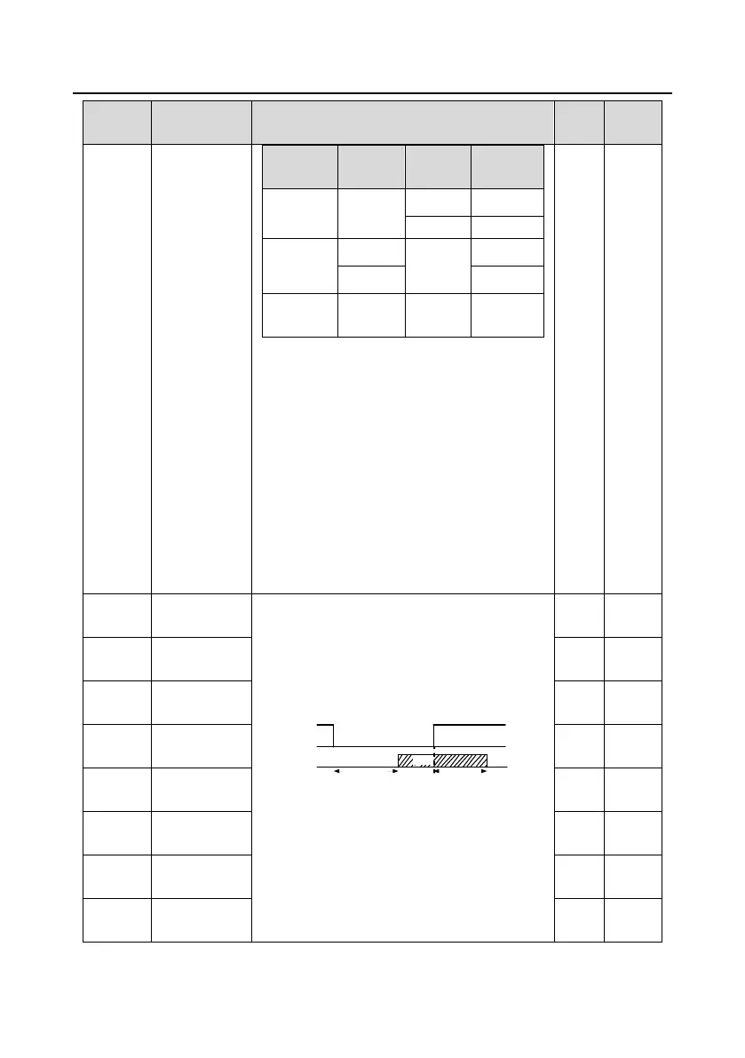
Used to specify the delay time corresponding to
the electrical level changes when the
programmable input terminals switch on or switch
off.
Si electrical level
Si valid
invalid invalid
Switch-on
delay
Switch-off
delay
valid
Setting range: 0.00050.000s
Note: After a virtual terminal is enabled, the state
of the terminal can be changed only in
communication mode. The communication
address is 0x200A.
0.000s
P05.13
S1 switch-off
delay
0.000s
P05.14
S2 switch-on
delay
0.000s
P05.15
S2 switch-off
delay
0.000s
P05.16
S3 switch-on
delay
0.000s
P05.17
S3 switch-off
delay
0.000s
P05.18
S4 switch-on
delay
0.000s
P05.19
S4 switch-off
delay
0.000s

Table of Contents

Related product manuals