Goodrive270 series VFD for fan and pump Function parameter list
-209-
continuously during the time (ignoring
proportional and differential function) to achieve
the max. output frequency (P00.03) or the max.
voltage (P04.31). Shorter integral time indicates
stronger adjustment.
Setting range: 0.00–10.00s
Used to determine the strength of the change
ratio adjustment on the deviation of PID
feedback and reference from the PID regulator.
If the PID feedback changes 100% during the
time, the adjustment of the differential regulator
(ignoring proportional and integral function) is
the max. output frequency (P00.03) or the max.
voltage (P04.31). Longer differential time
indicates stronger adjustment.
Setting range: 0.00–10.00s
Used to indicate the sampling cycle of feedback.
The regulator calculates in each sampling cycle.
A longer sampling cycle indicates slower
response.
Setting range: 0.001–10.000s
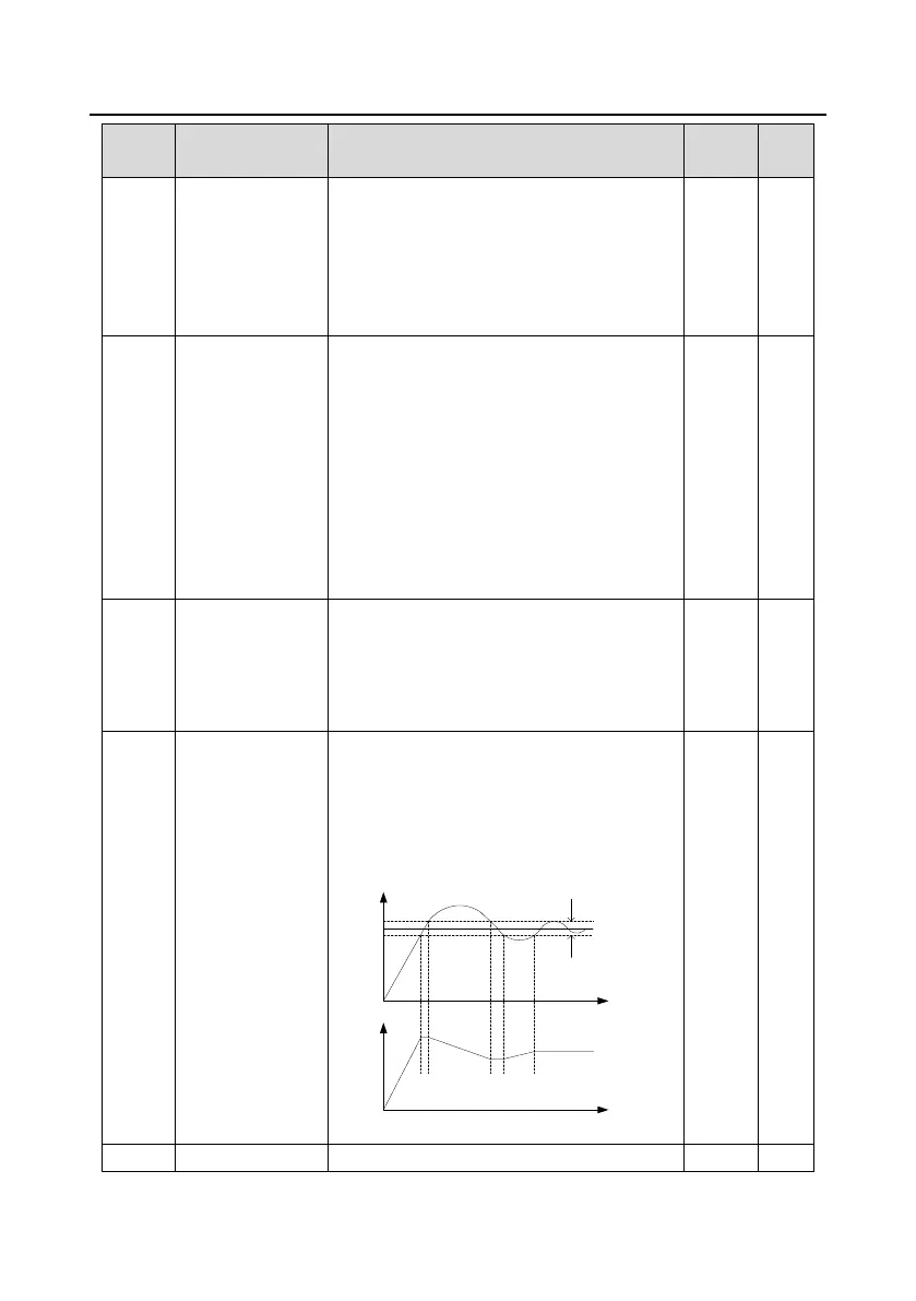
PID control
deviation limit
The output of the PID system is relative to the
max. deviation of the closed loop reference. As
shown in the following figure, the PID regulator
stops regulating in the range of deviation limit.
Set the function parameter properly to adjust the
accuracy and stability of the PID system.
Reference
Deviation
limit
Feedback
Output
frequency f
Time t
Time t
Setting range: 0.0–100.0%
The function codes are used to set the upper

 Loading...