Goodrive270 series VFD for fan and pump Installation guidelines
-21-
4.2.8.2 Points for attention
It is recommended that the cabinet adopts the nine-fold profile cabinet (PS cabinet). Before mounting
the VFD, install two bottom support crossbeams, a mounting bracket, and a mounting rail in the
cabinet, and design the mounting crossbeam for VFD fixing, and reserve fixing holes on the mounting
crossbeam (see C.4.3 Floor mounting dimensions for the specific location and size). Reserve the
in-cabinet space for connecting the copper bar coming out of the VFD side.
The VFD can be pushed into and out of the cabinet through the rail and four casters at the VFD
bottom. Note that The VFD can be pushed into or out of the cabinet only after the casters are aligned
with the rail. To ensure safety, arrange two people to push the VFD into or out of the cabinet.
Note:
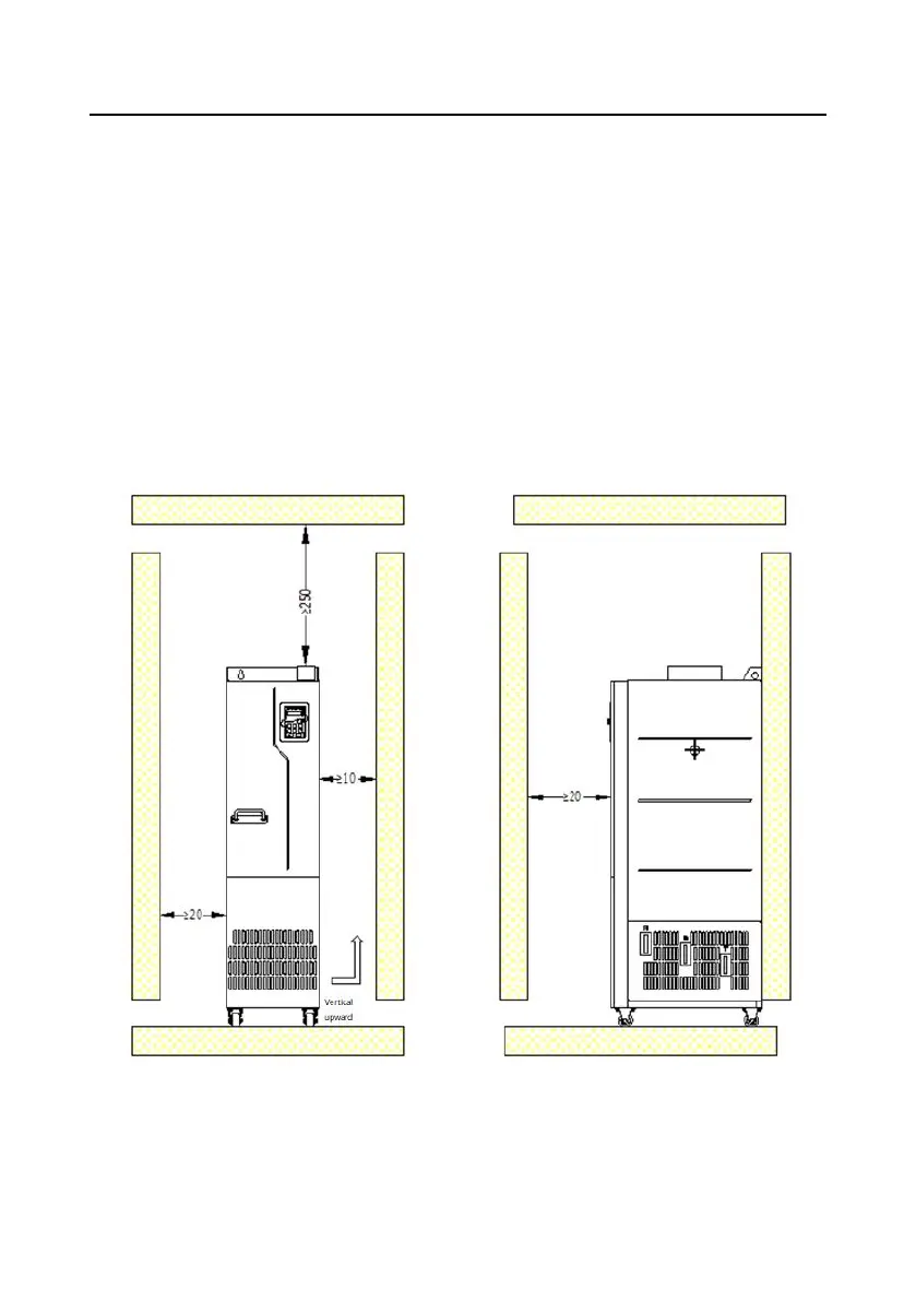
Figure 4-9 shows the mounting space. You not only need to reserve enough heat dissipation
space for the VFD but also need to consider the heat dissipation condition for other devices in the
cabinet.
Figure 4-9 Mounting space requirements
Cabinet air inlet actual effective area (indicating the through-hole area): For GD270-220-4(-Ln)
and GD270-250-4(-Ln), the air inlet area is 42210mm
2
and the air outlet area is 67875mm
2
; For

 Loading...