EasyManuals Logo

INVT Goodrive270 Series User Manual

INVT Goodrive270 Series
372 pages
To Next Page IconTo Next Page
To Previous Page IconTo Previous Page
Page #64 background imageLoading...
Page #64 background image
Goodrive270 series VFD for fan and pump Basic operation guidelines
-54-
Level 1
Level 2
Level 3
Level 4
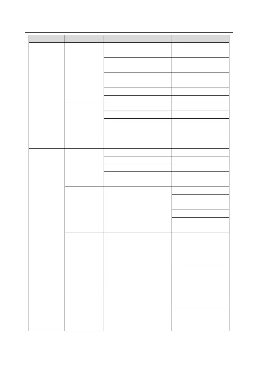
communication expansion card
2
P25: Input functions of
expansion I/O card
P25.xx
P26: Output functions of
expansion I/O card
P26.xx
P27: Reserved
P27.xx
P28: Master/slave control
P28.xx
Factory-defined
control function
group setting
P90: PID1 control
P90.xx
P91: PID2 control
P91.xx
P92: Real-time clock and timer
(available at use of LCD
keypad)
P92.xx
P93: Fire control
P93.xx
State
monitoring/fault
record
State monitoring
P07: HMI
P07.xx
P17: Status viewing
P17.xx
P18: Reserved
P18.xx
P19: Expansion card status
viewing
P19.xx
Fault record
/
P07.27: Present fault type
P07.28: Last fault type
P07.29: 2nd-last fault type
P07.30: 3rd -last fault type
P07.31: 4th -last fault type
P07.32: 5th-last fault type
Fault state
/
P07.33: Running
frequency at present fault
P07.34: Ramp reference
frequency at present fault
P07.xx: xx state of the last
but xx fault
Clear fault record
/
Sure to clear fault
records?
Modified
parameter
/
Pxx.xx has modified
parameter 1
Pxx.xx has modified
parameter 2
Pxx.xx has modified

Table of Contents

Questions and Answers:

Question and Answer IconNeed help?

Do you have a question about the INVT Goodrive270 Series and is the answer not in the manual?

INVT Goodrive270 Series Specifications

General IconGeneral
BrandINVT
ModelGoodrive270 Series
CategoryWater Pump
LanguageEnglish

Related product manuals