18
Inxpect SRE 200 Series| Instruction manual v1.5 DEC 2023 |Inxpect SAF-IM-200S_5m_7_00047_en_v1.5|© 2021-2023 Inxpect SpA
3. Get to know Inxpect SRE 200 Series
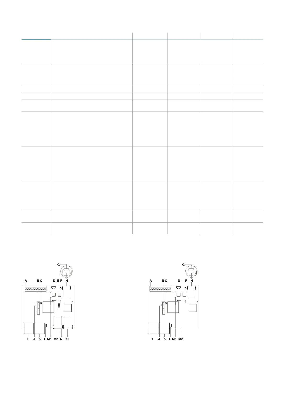
Part Description C201A-PNS C201A-F C202A C203A
G Fieldbus status LEDs
See "PROFIsafe Fieldbus status
LEDs" on page20 or "FSoE Fieldbus
status LEDs" on page20.
x x - -
H Ethernet port with LEDs for
connecting the PC, communicating
with the Inxpect Safety application,
and for MODBUS communication
x x x -
I Power supply terminal block x x x x
J Power supply LEDs (steady green) x x x x
K CAN bus terminal block for
connecting the first sensor
x x x x
L DIP switch to turn on/off the bus
termination resistance:
l
On (top position, default)
=resistance included
l
Off (bottom position) =
resistance excluded
x x x x
M1 Status LED of hardware functions of
the secondary micro-controller:
l
slow flashing orange: normal
behavior
l
other status: contact Technical
Support
x x x x
M2 Status LED of hardware functions of
the primary micro-controller:
l
off: normal behavior
l
steady red: contact
Technical Support
x x x x
N Fieldbus port no.1 with LEDs
(PROFIsafe or EtherCAT® IN)
x x - -
O Fieldbus port no.1 with LEDs
(PROFIsafe or EtherCAT® OUT)
x x
- -
Note: only for C201A-F: the processing direction is from the N connection to the O connection. In normal
operation, the device receives the data from the controller on N and sends the outgoing data on O.
3.2.5 Type B control units
C201B-P, C201B-F
C202B


 To Next Page