Hardware Manual
BMS Master 4 / 4.5
Ref.: IR14417 A 15.01.2018 Page 10/76
The master software and its parameters have to be adapted to the special battery
configuration. In exceptional cases a slave module may be modified to control three or four
cells. Controlling less than three cells is not possible.
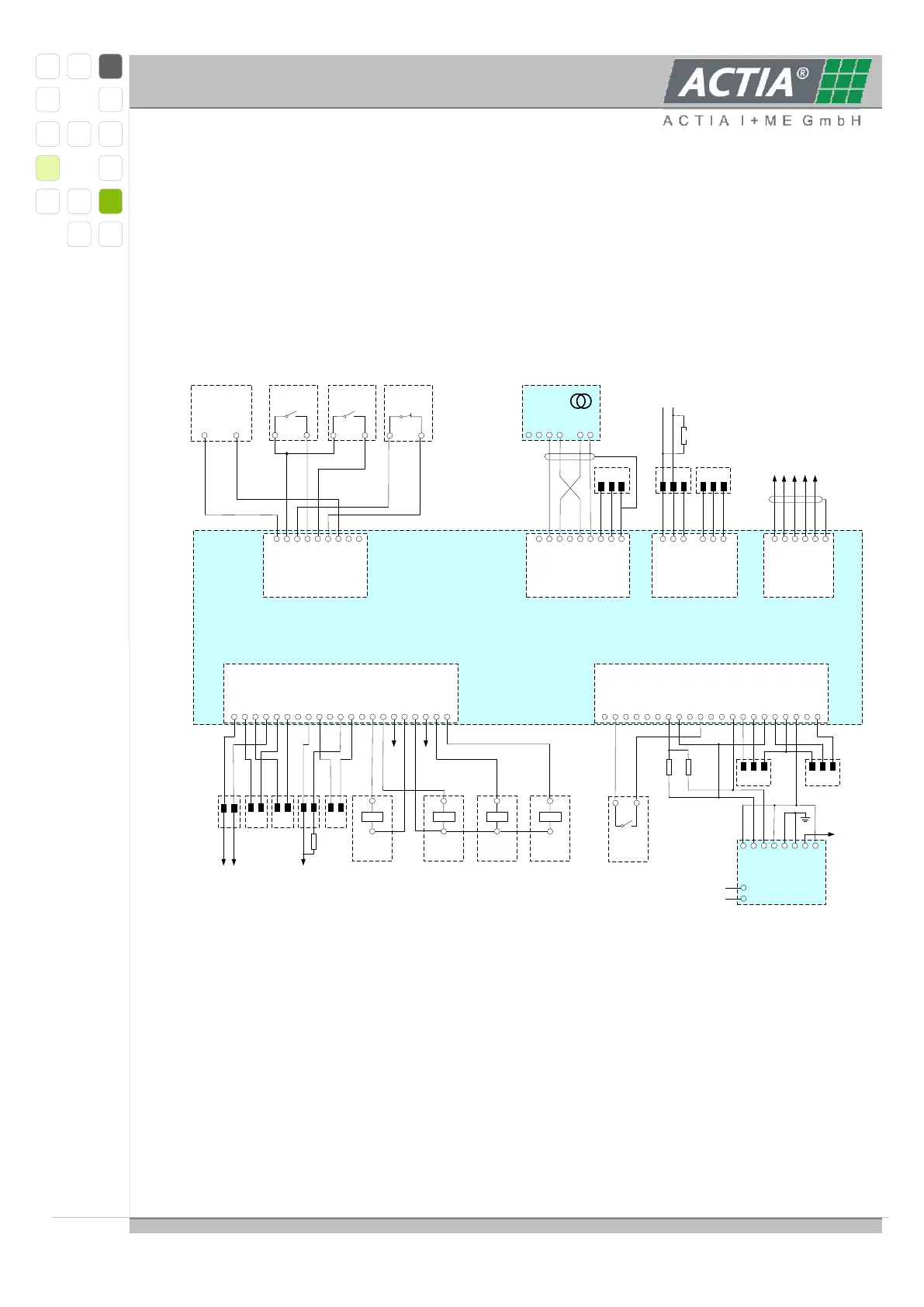
2.2 SCHEME „MASTER“
Example schematic diagram:
REL1A
1 2 3 4 5 6 7 8 9 10 11 12
SWO1
SWO2
REL1B
KL31
KL31
REL2A
SWO3
SWO4
REL2B
KL31
KL31
KL31
13 14 15 16 17 18 19 20 21
SWO5
SWO6
PWM0
KL31
KL31
AOUT
SWO7
SWO8
Outputs
KL30
1 2 3 4 5 6 7 8
KL30
KL30
Plug In
Drive
EMSRET
KL31
KL31
KL31
9
Supply
OIN1
1 2 3 4 5 6 7 8 9 10 11 12
DIN1
AIN1
OIN2
DIN2
AGND
7V
DIN3
AIN2
SS200
DIN4
AGND
FIN1
13 14 15 16 17 18 19 20 21
ICONst1
AIN3
FIN2
ICONst2
AGND
KL31
KL31
AIN4
7V
1 2 3 4 5 6 7 8
S1
K1
KL31
S2
K2
CAN2H
CAN2L
Shield
9
Current
CAN1H
1 2 3 4 5 6
CAN1L
Shield
CAN3H
CAN3L
Shield
CAN
BUS_A
1 2 3 4 5 6
5V NET
GND
BUS_B
FAIL_IN
Shield
Master
CAN 2
LiYCY- TP 2x2 0,25mm²
K1 & K2 twisted
S1 & S2 twisted
CAN 1 CAN 3
Master_Slave_BUS_A
Master_Slave_5V NET
Master_Slave_GND
Master_Slave_BUS_B
Master_Slave_FAIL_IN
PE
Ext. 12V
2,2 kΩ
2,2 kΩ
PT100 PT100
Out1 = FAN
Out2 = ?
Out3 = Error Signal
Out4 = ?
Out1 Out2 Out3 Out4
SavOut
HV-Relay
Charge ?
+
-
HV-Relay
minus
+
-
HV-Relay
precharge
+
-
HV-Relay
plus
+
-
PWM out
Anabg out
2nd Level Error
2nd Level Error
1 kΩ
Signal Error
1 2
SW5-8
OFF
Current sensor
VAC4645
K2
123456
K1
S2
S1
LC1
LC2
1 2
PlugIn
Power Supply
1 2
Vbat GND
1 2
Security
Switch
OK-
12345678
OK+
M+
M-
KE
E
A+
A-
IMD
L+
L-
Inputs
Slave Comm.
1 2
Drive
CANH
CANL
120Ω
Bat -
Bat +
IR 155-32-3201
The Master module covers the following functions:
Communicating with the connected slave modules
Providing and supervising time
Measuring of the total current drawn from the battery
Controlling the main power relay
Switching of climatic equipment, e.g. fans, Peltier elements or similar devices