Hardware Manual
BMS Master 4 / 4.5
Ref.: IR14417 A 15.01.2018 Page 11/76
VBAT-
Master_SlaveCom.1
BUS A
BUS B
5V
GND
SHIELD
SHIELD
BUS A
BUS B
5V
GND
Failn 1
Failn 2
Cell connector
SLAVE n
123456789101112
Master_SlaveCom.4
Master_SlaveCom.2
Master_SlaveCom.3
Master_SlaveCom.5
VBAT+
4,7 kΩ … 5,1 kΩ
123456789101112
BUS A
BUS B
5V
GND
SHIELD
SHIELD
BUS A
BUS B
5V
GND
Failn 1
Failn 2
Cell connector
SLAVE n-1
123456789101112
123456789101112
BUS A
BUS B
5V
GND
SHIELD
SHIELD
BUS A
BUS B
5V
GND
Failn 1
Failn 2
Cell connector
SLAVE 1
123456789101112
123456789101112
e.g. LiYCY- TP 3x2 0,25mm²
Bus A & Bus B Twisted
5V & GND twisted
1
2
3
4
5
6
NTC2-
NTC1-
PTC+
temperature
control
NTC
NTC
1
2
3
4
5
6
NTC2-
NTC1-
PTC+
temperature
control
NTC
NTC
1
2
3
4
5
6
NTC2-
NTC1-
PTC+
temperature
control
NTC
NTC
Communicating with external hardware via a high speed CAN interface
The Master module is supplied either by the controlled battery itself or it can be supplied by
an additional system battery, e.g. in mixed 12V/42V-systems.
System time and date are provided by a real time clock.
The Master supply voltage must not exceed 28 VDC.
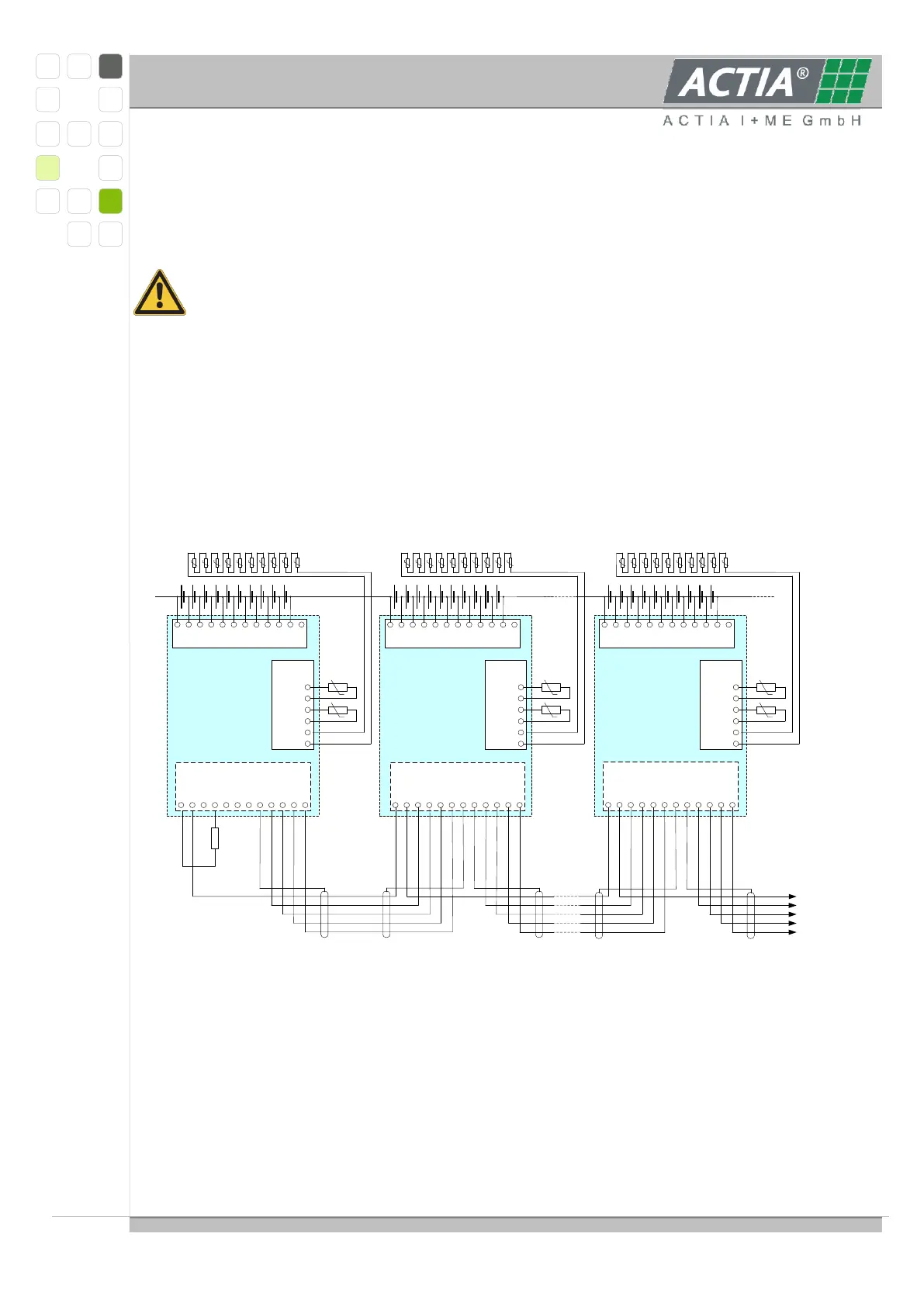
2.3 SCHEMATIC FOR SLAVE C, SLAVE 5
Example schematic diagram based on Slave C modules; for the Slave 5 modules the
picture is valid analogously. The Slave C, Slave 5 is on Master Connector CN106 (Slave
Comm) wired connected.
The slave module can be connected to 5 up to 10 cells and covers the following functions:
Communicating with the Master module
Measuring of the single cell voltages
Compensation of different cell charge states
Controlling of the mechanical integrity of one or more batteries
Measuring of temperatures
Signalling overvoltage and over temperature conditions