Hardware Manual
BMS Master 4 / 4.5
Ref.: IR14417 A 15.01.2018 Page 32/76
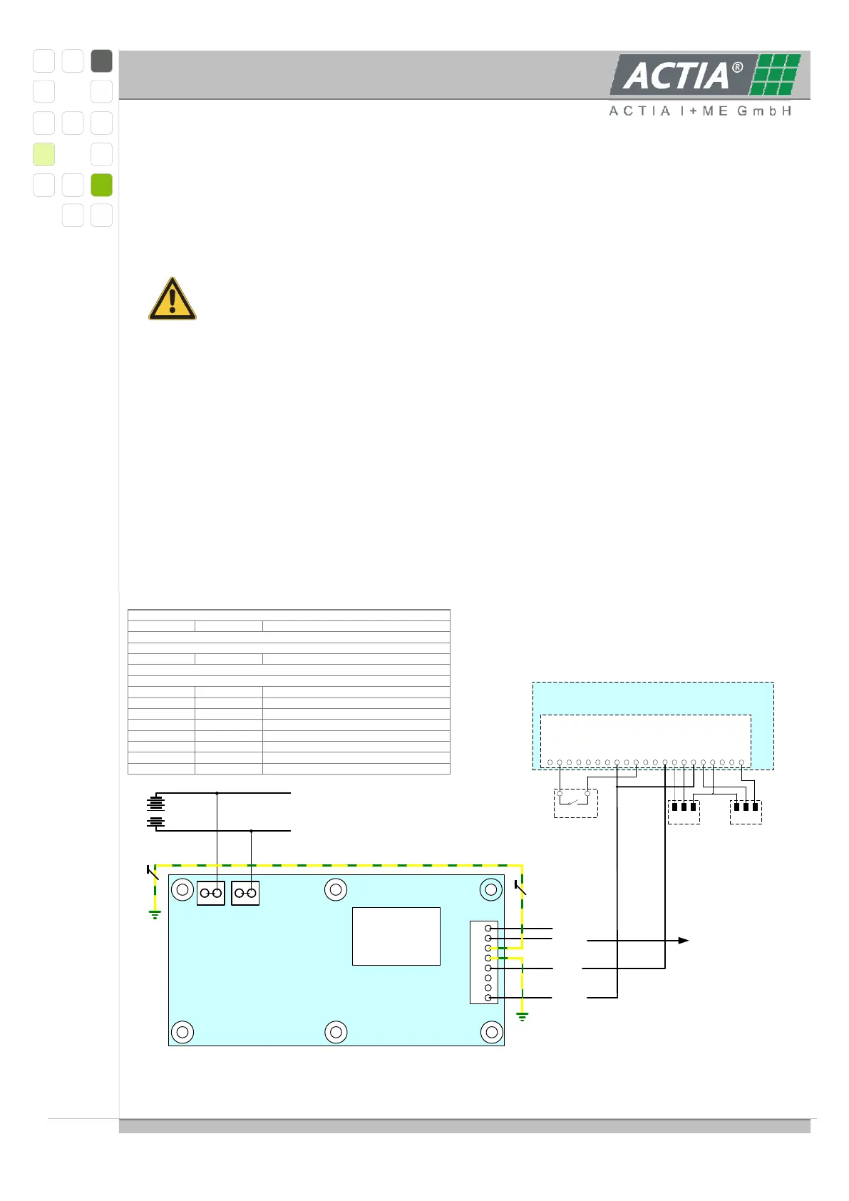
3.3 INSULATION MONITORING IR155-3204
The BMS MASTER is prepared for the cooperation with the Bender insulation monitor
IR155-3204.
Only one insulation monitoring device may be used in each interconnected
system. When insulation or voltage test are to be carried out, the device shall be
isolated from the system for the test period.
IR155-3204 Measurement Output Highside
Measurement of insulation resistance with modified DCP method
o Response time <2s for first estimated insulation resistance
o Response time <20s for measured insulation resistance
Detection of ground faults and lost ground line.
Short protected outputs for:
o Fault detection (high side output)
o Measurement Value (PWM 5…95%) & Status (f=10..50Hz) at high and
inverted low side output
1
2
3
4
5
6
7
8
1212
E
KE
A - ISOMETER
®
iso-F1 IP155-3204
KL31
OK
HS
KL15
KL31
M
HS
KL31b
L+
L-
OIN1
1 2 3 4 5 6 7 8 9 10 11 12
DIN1
AIN1
OIN2
DIN2
AGND
7V
DIN3
AIN2
SS200
DIN4
AGND
FIN1
13 14 15 16 17 18 19 20 21
ICONst1
AIN3
FIN2
ICONst2
AGND
KL31
KL31
AIN4
Ext. 12V
PT100 PT100
1 2
Pilotline
Inputs
Master 4
XLA+XLA-
XK1A
Pin 1+2
Connector XLA-
Connector XK1A
Connector XLA+
L+ Line Voltage
Pin 1+2 L- Line Voltage
Pin 2
Pin 1
KL15
KL31b Electronic ground
Supply voltage
Pin 4
Pin 3
KL31
KL31 Chassis ground
Chassis ground (sep. line)
Pin 6
Pin 5 M HS Data Out, f, PWM (high side)
Pin 8
Pin 7
OK HS
Status Output (high side)