Hardware Manual
BMS Master 4 / 4.5
Ref.: IR14417 A 15.01.2018 Page 35/76
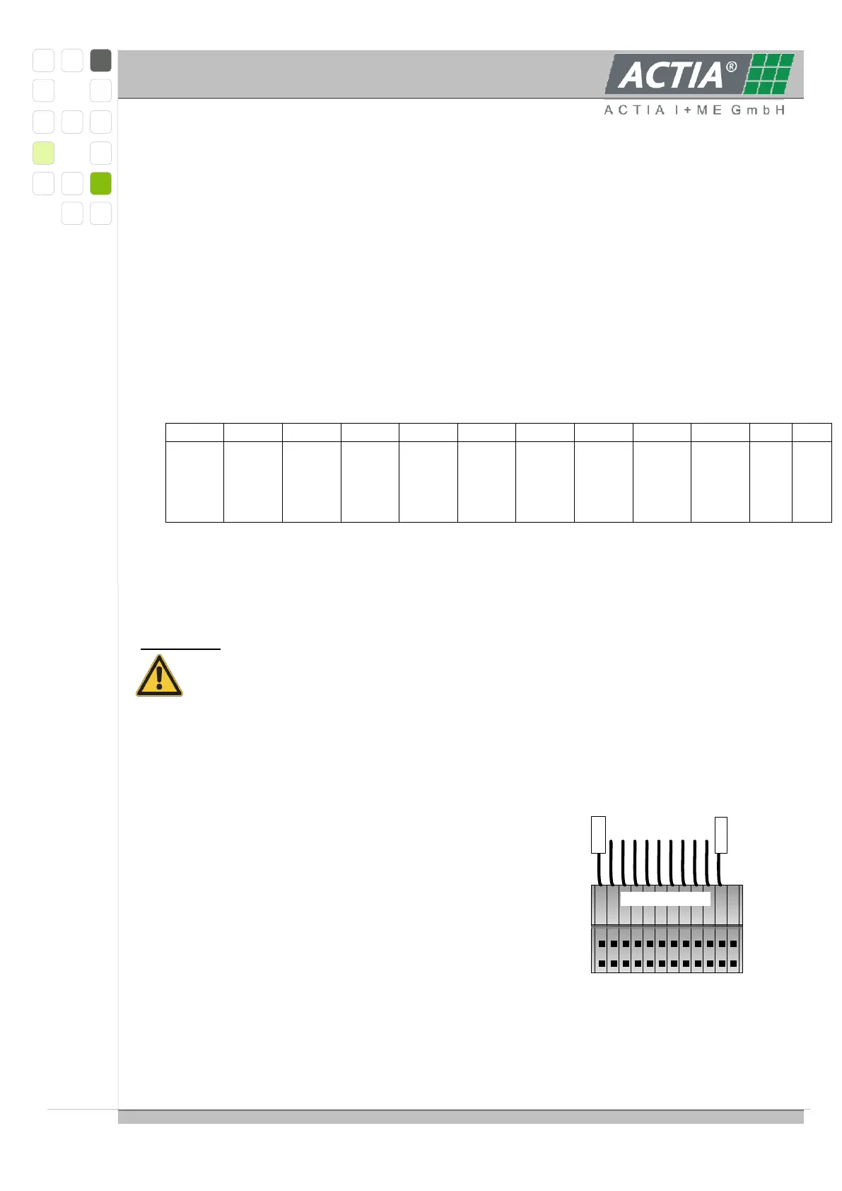
12 11 10 9 8 7 6 5 4 3 2 1
10-cell-wiring
Z10+
Z1-
3.4.4. FUNCTIONAL DESCRIPTION
3.4.4.1 POWER SUPPLY
The CPU and peripherals are supplied by linear regulated 5VDC derived from the mid cell
voltages number 6 to 8, min. 5.4V to 12.6V, connected to cell contacts 7 … 10.
The power supply reference level is always at cell contact 7.
3.4.4.2 SINGLE CELL INTERFACE
The interface to the single battery cells is realized as 12 edge connector pads suitable for an
edge connector ZEC1, 0/12 made by Phoenix Contact (Order No. 18 93 78 2), additionally
12 solder pads in a 3,5mm-pitch for 10 cells with 11 connections; order with contact row at
top of board; pin1 is the last one right of the coding slot.
The edge connector provides pre-mating contacts to assure the proper connecting
sequence. Do only connect the single cell voltages to the edge connector, when it is not
plugged.
Attention:
If NOT using the edge connector, the single cells have to be connected in a
proper sequence to avoid damage to the multiplexers on the slave module. The
cells can be connected in two ways:
- either by soldering the wires directly into the pad holes
- or by using pin rows in 3.5 mm pitch in conjunction with pluggable miniature spring
cage clamps (e.g. PHOENIX CONTACT PST 1,0/12-3,5 (Order No. 19 45 19 3) with
clamps FK-MPT 0,5/12-ST-3,5 (Order No. 19 14 03 0))
For Phoenix connector details see product catalogue or visit www.phoenixcontact.com.
The following sequence must be strictly observed:
1. contact 12
2. contact 6
3. contact 9
4. contact 2
5. contact 7
6. the remainder in any order
To remove the slave from the battery, disconnect in
reverse order.