Hardware Manual
BMS Master 4 / 4.5
Ref.: IR14417 A 15.01.2018 Page 16/76
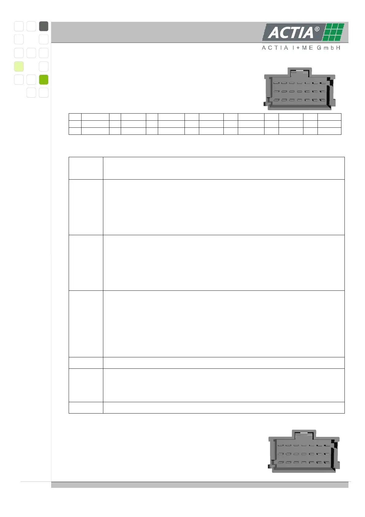
3.1.3.2 OUTPUTS, CONNECTOR CN102
The device has 12 outputs with different characteristics.
Connector pin assignment / View on the pins:
Nomenclature:
Minus, Ground, reference level – for all loads connected to outputs SWOx
(relays, valves, motors etc.)
Switch outputs; if activated the voltage level corresponds to KL30 level; if
not activated the output level is 0 … 7 V depending on load resistance, due
to a test current of some micro amps to detect open loads in OFF-state.
The outputs may be loaded with up to 2.5 A each (peak 4 A for 1 second).
Total of outputs SWO1…4 must not exceed 5 A.
Switch outputs with same characteristic as outputs SWO1…4.
Outputs SWO5…8 will be activated only, when EMSRET is connected to
KL30 in any way.
The outputs may be loaded with up to 2.5 A each (peak 4 A for 1 second).
Total of outputs SWO1…4 must not exceed 5 A.
potential free relay contact, can carry 30V / 2A resistive and inductive.
The relay will be cut off, when
- input DIN1 is deactivated or
- a FAIL-signal from any of the cell monitoring slave moduls is pending
The relay can/should be included together with the emergency stop switch
into a security chain .
potential free relay contact, can carry 30V / 2A resistive and inductive
pulse width modulated output;
output voltage U
PWM
(KL30-level – 3.5V, max 10V), max.50 mA,
min. pulse width t
min
50 µs
analog output U
AOUT
0… (KL30-level – 3.5V, max 10V), max.50 mA
3.1.3.3 INPUTS, CONNECTOR CN103
The device has 12 inputs with different characteristics.
1
2
3
4
5
6
7
8
9
10
11
12
13
14
15
16
17
18
19
20
21
1
2
3
4
5
6
7
8
9
10
11
12
13
14
15
16
17
18
19
20
21