Hardware Manual
BMS Master 4 / 4.5
Ref.: IR14417 A 15.01.2018 Page 39/76
Connector Assignments,
Pin numbers counting from
top to bottom with the
PCB battery interface on top.
See chapter 3.4.3
ATTENTION: Via the cell voltages the temperature sensor is
connected to the battery cells. So its potential to GND may exceed
several hundreds of Volts depending on the number of cells.
A sufficient insulation of the sensor and its cables is
imperative!
3.4.4.8 SIGNALLING LEDS
Two signalling LEDs are connected to CPU-ports. 10 LEDs show the status of the balancing
resistors. The centred four of those display the Slave address.
3.4.4.9 2ND LEVEL VOLTAGE DETECTION
All single cell voltages are controlled by “second level security chip” activating the isolated
fault port when at least one cell voltage exceeds 4.40 V for longer than 1 second (other cut-
off voltages are possible depending on the selected chip type; feasibility depends on
quantities). This circuitry is always active and cannot be deactivated, though for test
reasons the fault output may be activated by software.
3.4.4.10 FAULT MESSAGING INTERFACE
The fault messaging interface is isolated and realized as an open collector output referenced
to NETGND level. Current sink capability is appr. 2 mA.
The FAILn–lines are to be connected in parallel from one slave module to the next resp. to
the appropiate master input (MASTER), so all FAILn–outputs are OR-wired together.
At the end of the Slave chain the FAILn-line has to be terminated with a resistor of 4.7 kΩ
or 5.1 kΩ to the +5VNET.
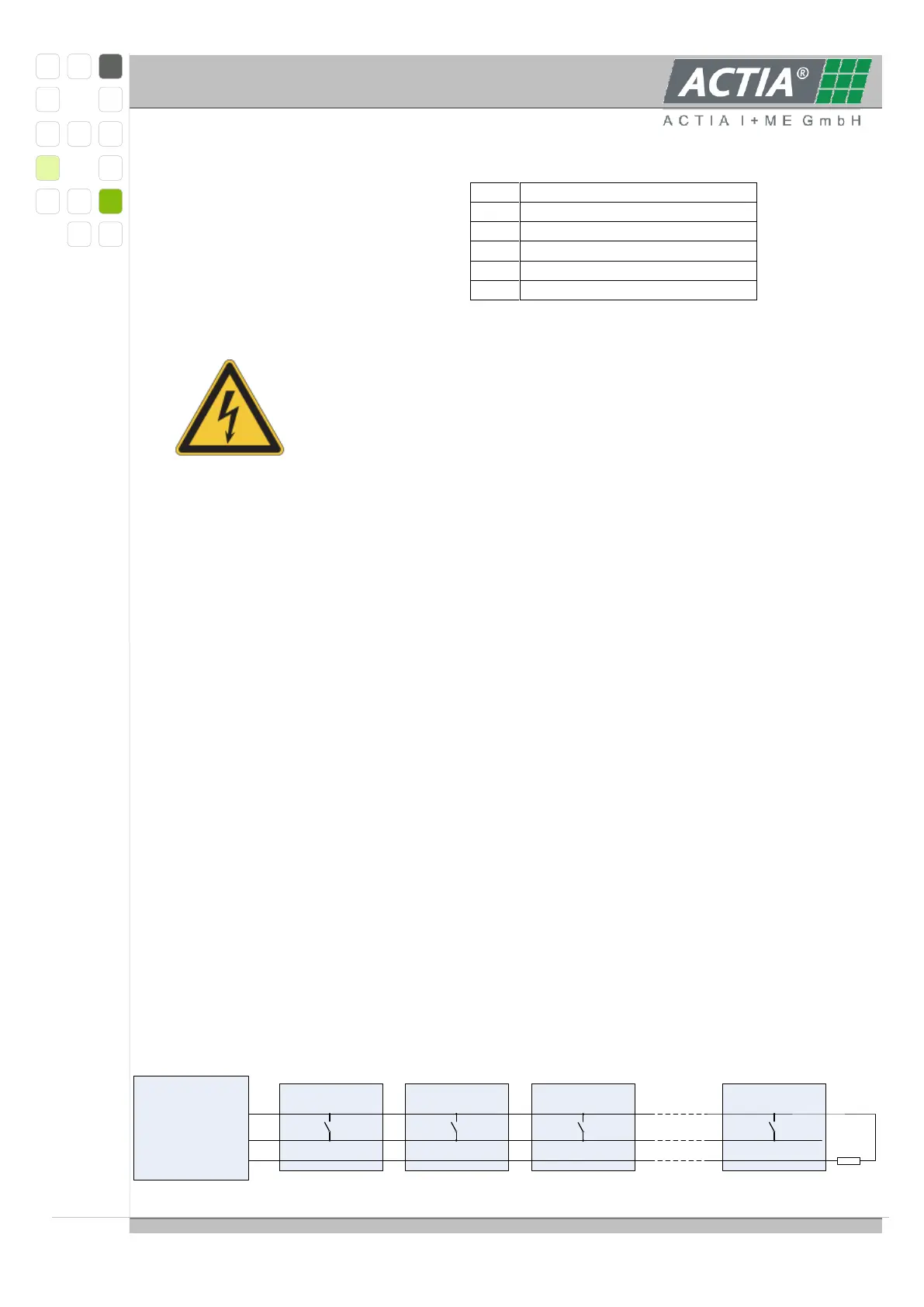
Connection sketch for the FAILn-lines (MASTER with SLAVE_C):
Master Module
1. Slave Module 2. Slave Module 3. Slave Module Letztes Slave Module
5V
Failn 1 Failn 2
4,7 kΩ … 5,1 kΩ
FAIL_IN Failn 1 Failn 2Failn 1 Failn 2Failn 1 Failn 2
5V5V5V5V5V5V5V5V NET
GND GNDGND GND GNDGND GND GND GND