Hardware Manual
BMS Master 4 / 4.5
Ref.: IR14417 A 15.01.2018 Page 23/76
3.1.6. ELECTRICAL SPECIFICATION
Sleep Mode, Master OFF, KL 30
Standby/Operating, Master ON, KL
30, KL 15 ON
Voltage Real Time Clock Data
Retention
RTC data retention time with no
KL30 supply
Sleep Mode,
KL15 OFF, CAN-Wakeup OFF
@12V Master4
@12V Master 4.5
Standby,
no communication,
no output activated
@12V Master4
@12V Master 4.5
Operating,
CAN & RS485 communication,
no output activated
@12V Master4
@12V Master 4.5
Operating
maximum load input current
CAN and Slave communication
All Outputs ON
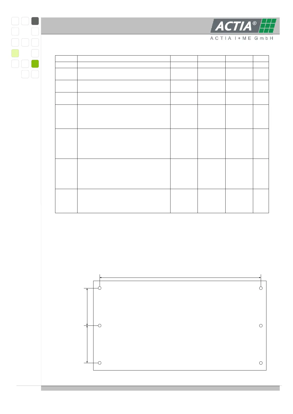
3.1.7. HOUSING
The housing is made of two parts of tinned and powder coated steel plate, degree of
protection IP30 (apertures < 2.5 mm), total size approximately 120 x 230 x 36 mm
(without connectors).
Device mounting with 6 screws or bolts M3;
Drilling plan: