Hardware Manual
BMS Master 4 / 4.5
Ref.: IR14417 A 15.01.2018 Page 45/76
3.5.4. FUNCTIONAL DESCRIPTION
3.5.4.1 SUPPLY
CPU and peripherals are supplied with a linear regulator with 5V
DC
out of cells 6, 7 und 8,
(connector pins 3, 16, 4, 17) from 5.4 to 12.6 V
DC
.
The internal reference point for all voltages is always connector pin 3; except the
isolated region of the RS485 interface which is referenced to NETGND.
3.5.4.2 CONNECTING BATTERY CELLS
The interface to the single battery cells is part of the 24-pole connector. Only pins 1 to 9
and pins 13 to 18 and pins 20/21 may be used connecting cell voltages and temp sensors.
3.5.4.3 CONNECTING LESS THAN 10 CELLS
For connecting less than 10 cells, the non-existing cells have to be replaced by shorting
wires according following scheme:
|---------|---------|---------|
As the crimp contacts are not suitable for crimping two or more wires the short circuits
have to be realized outside the connector housing. The shorting wires have to be as short
as possible; best by soldering and insulated with heat shrink.
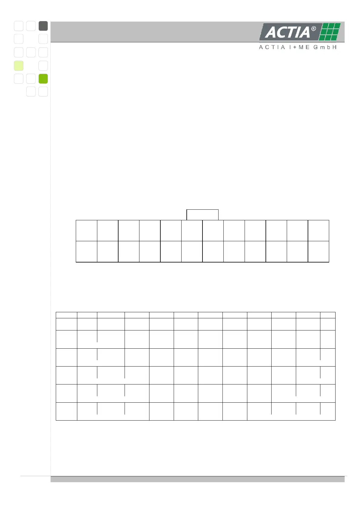
24 23 22
21
NTC2
20
NTC-GND
19
(testpoint)
18
Z10+
17
Z8+/9-
16
Z6+/7-
15
Z4+/5-
14
Z2+/3-
13
Z1-
12 11 10
9
NTC1
8
NTC-GND
7
PTC
6
PTC-GND
4
Z7+/8-
3
Z5+/6-
5
Z9+/10-
2
Z3+/4-
1
Z1+/2-
Slave_5 pin assignment 24-pole connector
view on cable side
standard assignment for cell voltages and temperature sensors