Hardware Manual
BMS Master 4 / 4.5
Ref.: IR14417 A 15.01.2018 Page 51/76
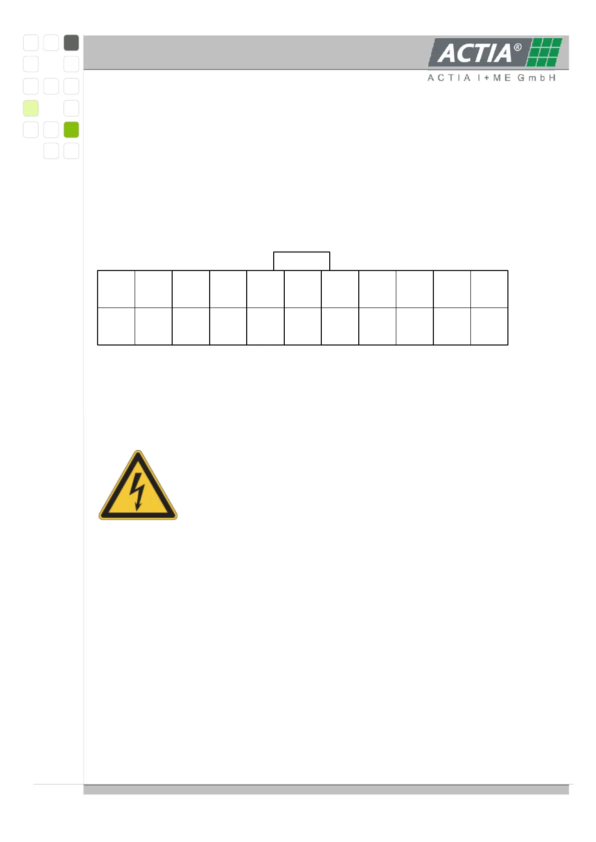
The sense lines to the single cell voltages may be connected ONLY to the 24-pole connector;
external balance resistors may be connected ONLY to 22-pole connector. The pins 1 … 10 of
the 22-pole connector may be used only, when there is no other possibility to connect the
balance resistors directly to the cell contacts.
3.5.6. INTERFACE ISOLATION
The interfaces to MASTER, RS485- and FAIL-interface, are optically isolated with air and
creepage distances of ≥ 10 mm, sufficient for voltages up to 1000 VDC at pollution level 1.
ATTENTION: The mounting holes do NOT comply with the
requirements of 10 mm air and creepage distances for high voltages.
If the slave modules are used under these conditions
non-conductive screws and/or bolts must be used.
3.5.7. MECHANICAL DIMENSIONS
Module size 80.5 x 97 x 17 mm
four mounting holes for M3-screws, symmetrically arranged in the corners, distances
67 x 83.5 mm
3.5.8. SUPPLY AND CURRENT CONSUMPTION
Supply voltage: 5.4 to 12.6 V (by three cells of the supervised battery)
Current consumption:
Average consumption with MASTER active, no balancing ~ 10 mA
21
R1
20
R2
19
R3
18
R4
17
R5
16
R6
15
R7
14
R8
13
R9
12
R10
10
Z1+/2-
9
Z2+/3-
8
Z3+/4-
7
Z4+/5-
6
Z5+/6-
4
Z6+/7-
3
Z7+/8-
5
Z6+/7-
2
Z8+/9-
1
Z9+
SLAVE_5 pin assignment 22-pole connector
view on cable side
assignment for cell voltages and external balance resistors
22
do not use
11
do not use
 Loading...