Hardware Manual
BMS Master 4 / 4.5
Ref.: IR14417 A 15.01.2018 Page 55/76
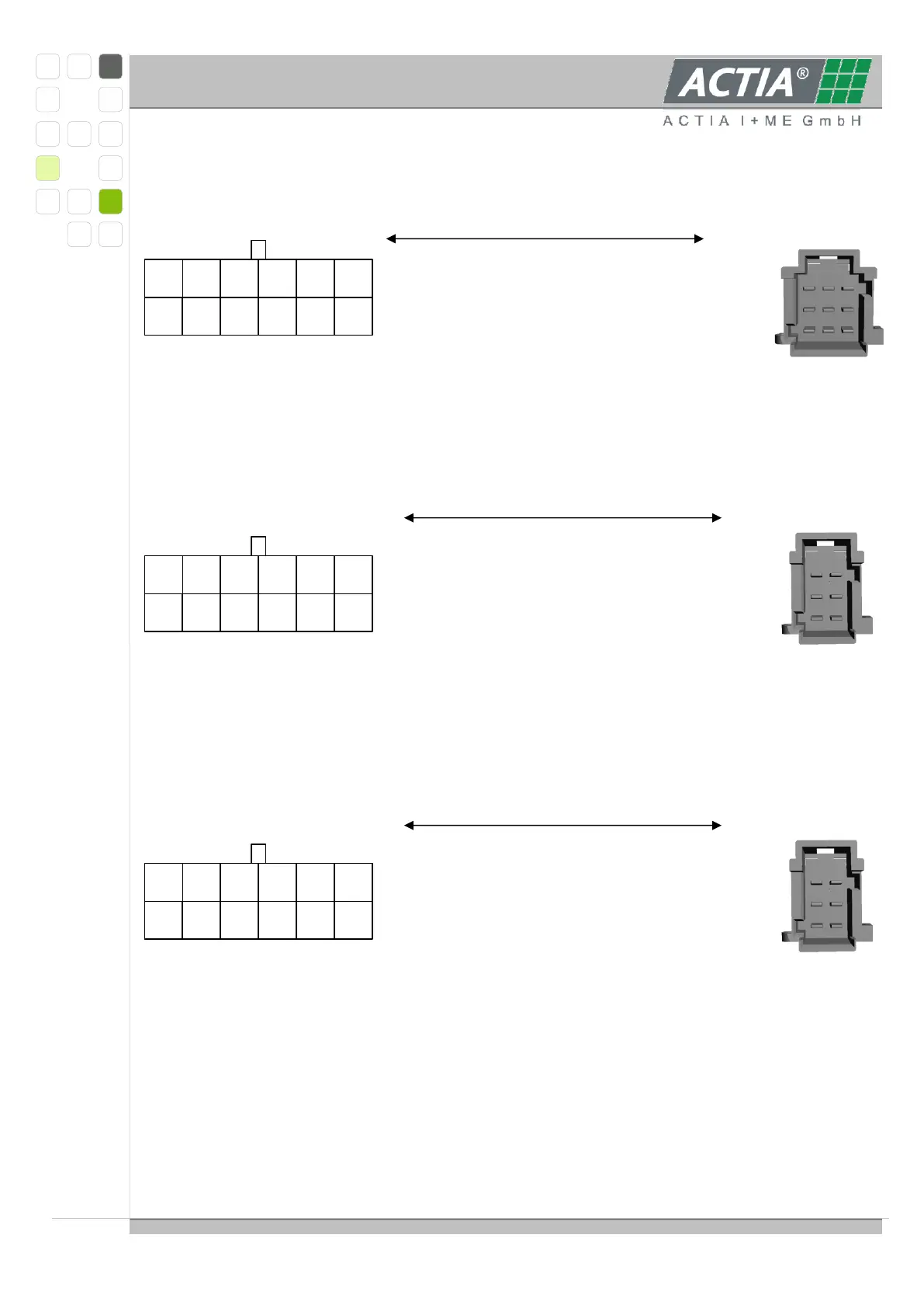
3.6.5. CONNECTING THE SLAVE 6 CON MODULE TO MASTER
Molex MicroFit 12-pol (view of the connector at the device) CN104 Tyco 9-pol
For CAN-H and CAN-L usage of twisted pair cables is required. The shield is connected to
the BMS Master only.
Usage of one CON Module
Molex MicroFit 12-pol (view of the connector at the device) CN106 Tyco 6-pol
For Fail A and Fail B are twisted pair cables used. The FAIL Pin is connected with a 4.7 …
5.1 kOhm resistor to 5VNET (pullup resistor).
Usage of more than one CON Module
Molex MicroFit 12-pol (view of the connector at the device) CN106 Tyco 6-pol
The FAIL Pin is connected with a 4.7 … 5.1 kOhm resistor to 5VNET (pullup resistor).
6
FAIL_
5
FAILA
4
CANH
3
CANH
2
TERMH
1
VNET
7
GND
8
TERML
9
CANL
10
CANL
11
FAILB
12
Shield
6
FAIL_
5
FAILA
4
CANH
3
CANH
2
TERMH
1
VNET
7
GND
8
TERML
9
CANL
10
CANL
11
FAILB
12
Shield
6
FAIL_
5
FAILA
4
CANH
3
CANH
2
TERMH
1
VNET
7
GND
8
TERML
9
CANL
10
CANL
11
FAILB
12
Shield