Hardware Manual
BMS Master 4 / 4.5
Ref.: IR14417 A 15.01.2018 Page 13/76
3. HARDWARE
3.1 THE HARDWARE OF THE MASTER
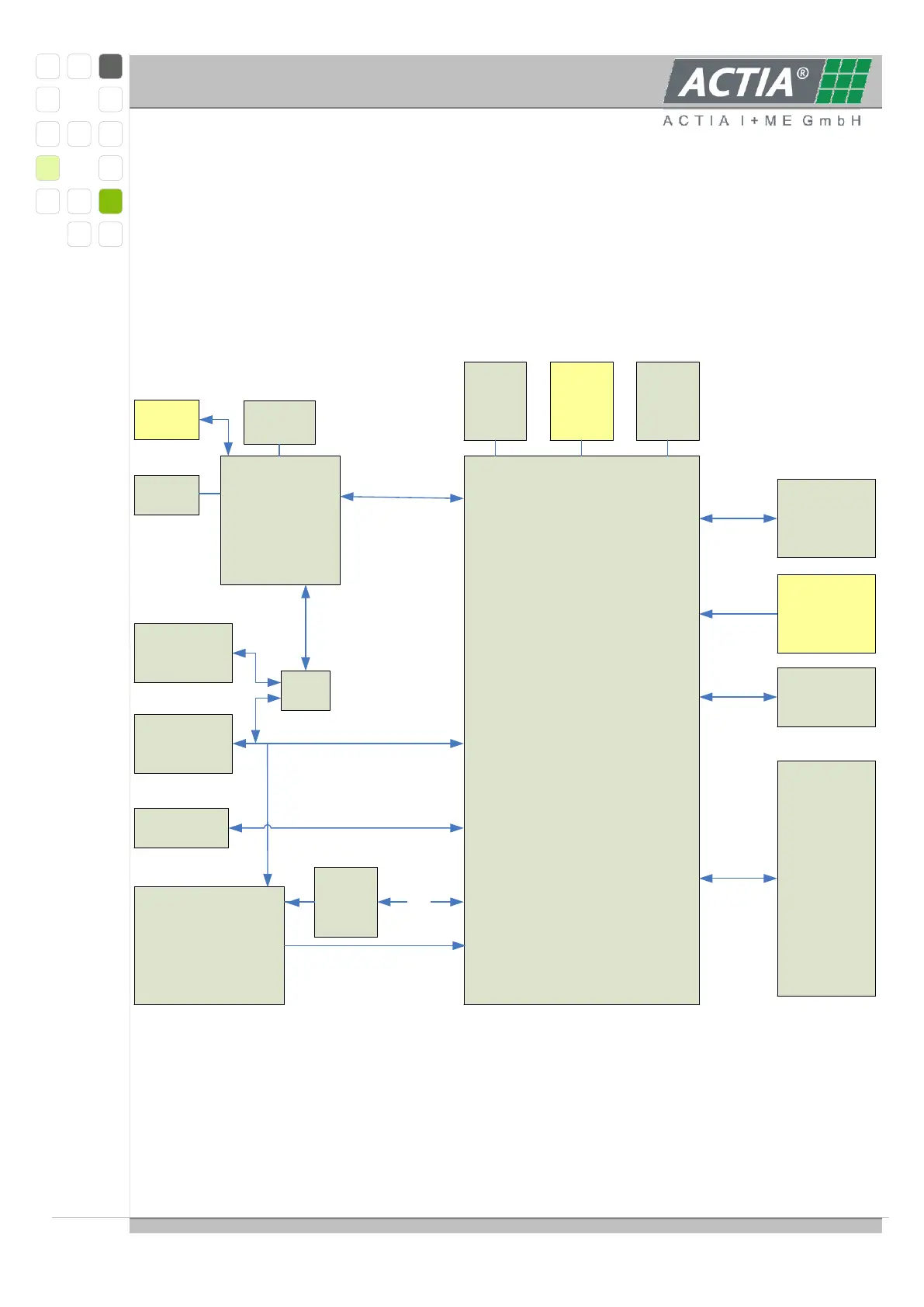
3.1.1. BLOCK DIAGRAM
This diagram shows the basic components of the „MASTER“
256kFlash
2 x CAN
2 x UART
ext
.
SRAM
VAC Current
sensor Interface
Opt. for other
sensor types
CAN
Transceiver 2
CAN
Transceiver 1
Slave Bus
RS485 Comm.
incl. Emerg
Fail
EEROM
IO Interface
512k Flash
1 x CAN
1 x UART
1 x Ethernet
RS 232
Interface
Ethernet
Power Supply
Voltage Limiter
RTC Wake UP
KL15 Wake UP
CAN Wake UP
RTC
Ext. Flash
USB Port
optional
2 x 4 MB
SDFlash
CAN
Transceiver 3
CAN
Mux
2 x 16 kB
8 x Out HiSide
2 x Relay OUT
6 x DigIN
1 x PWMOUT
4 x AnalogIN
1 x AnalogOUT
2 x ConstCur
I²C
handshake
Auxiliary
Microcontroller
Main
Microcontroller
Intern
Comm
The BMS-MASTER is equipped with two microcontrollers: the main processor XC167CI (by
Infineon) and the auxiliary processor AT91SAM7 (by Atmel). Both processors
communicate via internal interface or CAN-Bus.