Hardware Manual
BMS Master 4 / 4.5
Ref.: IR14417 A 15.01.2018 Page 20/76
1
6
5
9
1 – DCD
2 – RXD
3 - TXD
4 – DTR
5 – Masse
6 – DSR
7 – RTS
8 – CTS
9 - RI
Input for failure signals from any slave module caused by over
temperature on any slave module or by overvoltage of > 4.4V at any
single cell for longer than 1 second;
Activated by voltage < 2.4 V, input resistance 22 kΩ;
all FAIL outputs of all slave modules are connected together, a 5V/1mA-
current source must be realized with a resistor of 4.7 kΩ … 5.1 kΩ
connected to 5VNET on the last slave module in the chain.
The use of shielded and twisted pair cable is strongly recommended.
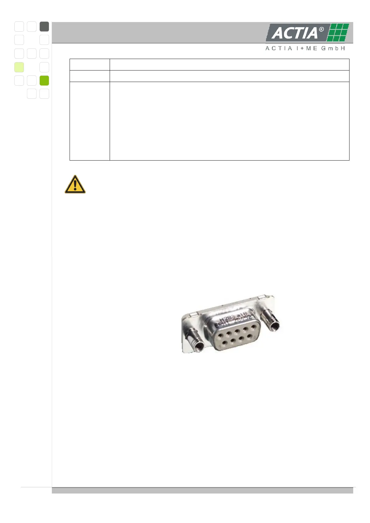
3.1.3.7 RS232-INTERFACE
The RS232-interface for software development, firmware download and diagnostics is
realized with a DSUB-9 female connector at the front side with standard pinning using
signals TXD, RXD, DTR, RTS und GND.
An active DTR-signal (> 2V) generates a system reset (RESET Mode).
An active RTS-signal (> 2V) in connection with reset leads the XC167 into bootstrap
mode.
Connector pin assignment:
Remark:
Is the serial Interface for monitoring used, the DTR signal line (Pin 4) should inactive set
or not connect (to prevent to keep the processor in the reset state). For a safe inactive
DTR signal put DTR signal line to Ground (e.g. EMC problems).
3.1.3.8 ETHERNET- INTERFACE
The Ethernet-interface is realized as 10/100 Base TX RJ45 tab-down 8-pin with internal
magnetics at the front side; the connector is suitable for AutoMDI(X). On both sides of the
jack a status-LED is placed.