Hardware Manual
BMS Master 4 / 4.5
Ref.: IR14417 A 15.01.2018 Page 66/76
Balance current
cell type
U [mV]: 1500 … 2800
I [mA]: 73 … 137
Cell type: LTO cell
U [mV]: 2500 … 3600
I [mA]: 91 … 131
Cell type: LFP cell
U [mV]: 2800 … 4200
I [mA]: 75 … 112
Cell type: NCA cell
The resistor values are adapted on the voltage range of the cell voltages. Thus an
optimum between maximum balance current and maximum board temperature is reached.
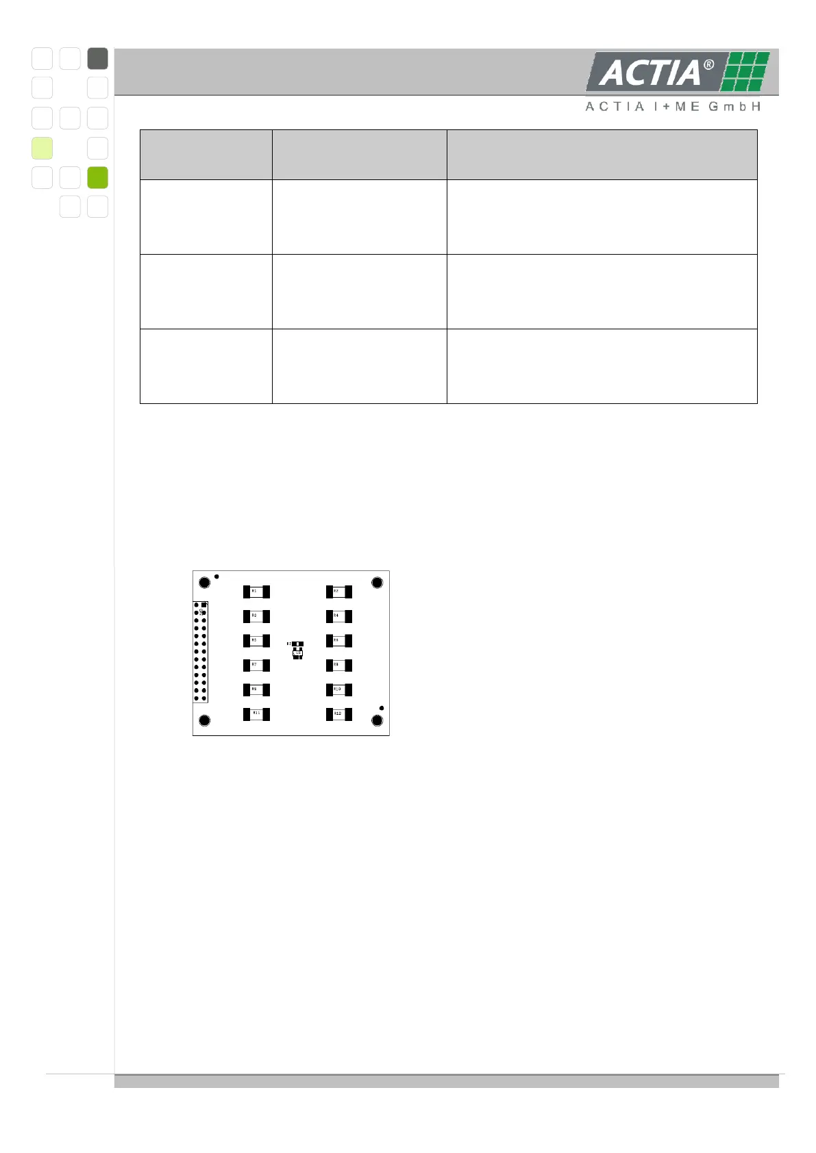
View of a Balance module to connect on the ANA module:
3.6.9.1 CONNECTION OF EXTERNAL BALANCE RESISTORS
All resistor respective cell connections are connected to a 24 pole MicroFit connector. At
this connector it is possible to connect external balance resistors to use higher balance
current max. 600mA. External resistors can be connected of 2 ways.
One connection direct at the cell, one connection with a separate wire at the 24
pole connector.
or
With 2 wires at the 24 pole connector
The cell voltage connections of the 12 pole connector must not use for the external
balance resistors. Wire gauge should be minimum 0.5 mm².
Resistor value is set depending to cell type, so that the balance current lower than