Hardware Manual
BMS Master 4 / 4.5
Ref.: IR14417 A 15.01.2018 Page 57/76
The communication cables must be shielded twisted pair. The signal pairs B1/B2 and
T1/T2 may not be exchanged; T1 connects to B1 and T2 connects to B2 of the next
module. The return signals (signal SI+-B) are only present if the hardware error detection
recognizes no error.
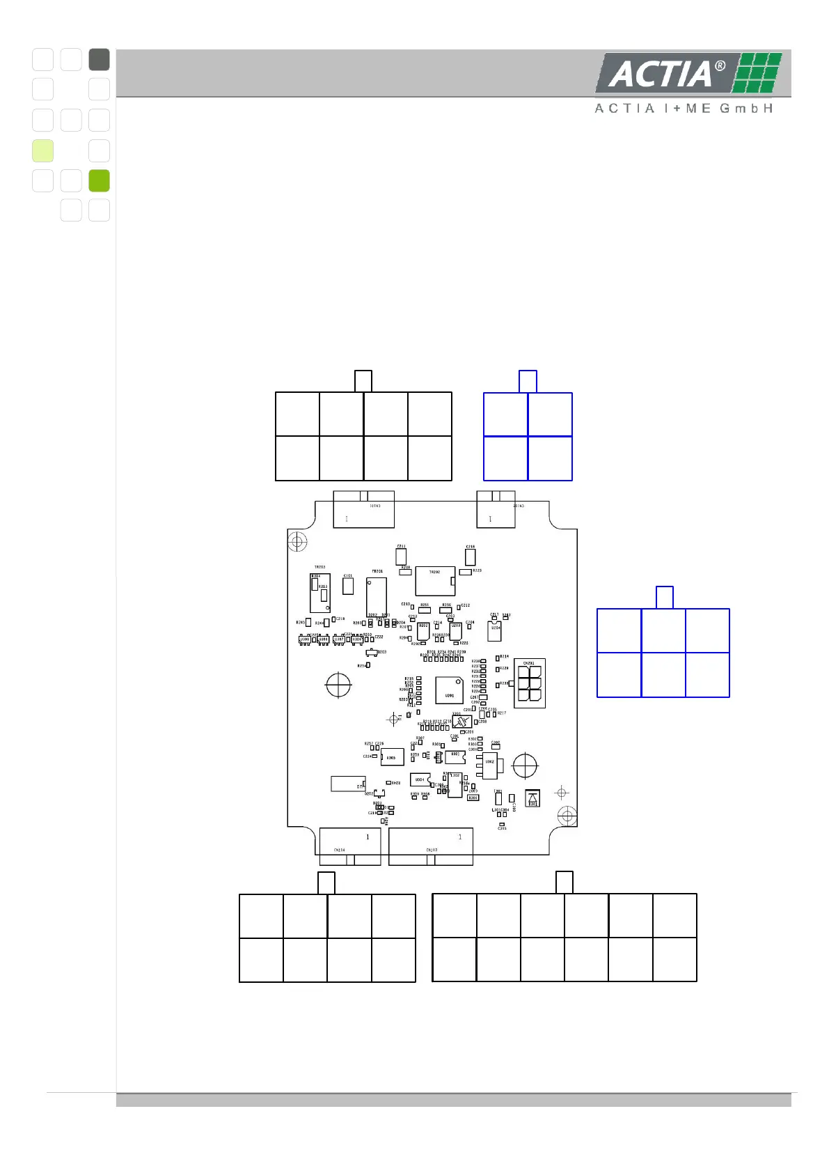
3.6.7. SL6_CON MODULE
3.6.7.1 LAYOUT AND CONNECTORS
8-pole connector to the lowest A module, view of
the connector at the device
6
Shield
5
T2A
4
SI+T
3
EN+T
2
Shield
1
T1A
7
EN-T
8
SI-T
4 pole connector to the lowest B module, view of
the connector at the device (future development)
4
Shield
3
T2B
2
Shield
1
T1B
6
FAIL_
5
FAILA
4
CANH
3
CANH
2
TERMH
1
VNET
7
GND
8
TERML
9
CANL
10
CANL
11
FAILB
12
Shield
12 pole connector to BMS Master, view of the
connector at the device
6
MD0
5
GND
3
+5V
2
TxD
4
RES
1
RxD
6 pole connector for programming,
view of the connector at the device
(only development)
4
GND
3
GND
2
GND
1
KL30
(+)
5
KL30
(+)
6
SW 1
7
SW 2
8
GND
8 pole connector for relay outputs, view of the
connector at the device