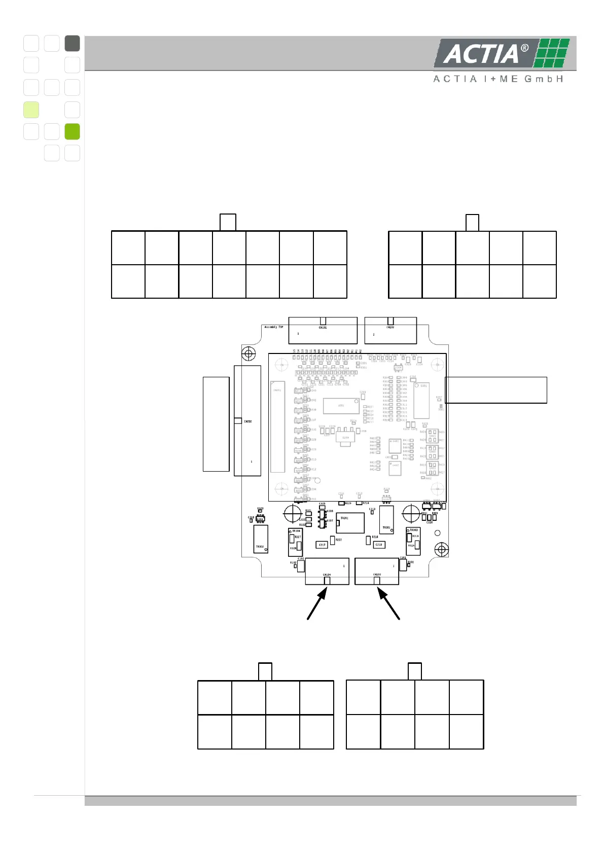
3.6.8. SL6_ANA MODULE
Connector for external balance
board 500mA max.
10
Sensor
5
9
Sensor
4
8
Sensor
3
7
Sensor
2
6
Sensor
1
4
Sensor
4
3
Sensor
3
5
Sensor
5
2
Sensor
2
1
Sensor
1
14-pole connector, cell voltage, view of the
connector at the device
10-pole connector, temperature sensor, view of the
connector at the device
8-pole connector to previous module,
view of the connector at the device
8-pole connector to the next module, view of the
connector at the device
6
Shield
5
B2
4
SI+B
3
EN+B
2
Shield
1
B1
7
EN-B
8
SI-B
6
Shield
5
T2
4
SI+T
3
EN+T
2
Shield
1
T1
7
EN-T
8
SI-T
SL6_R- module with balance resistors
app. 90 mA
14
n.c.
13
CV11
5
CV8
4
CV6
3
CV4
2
CV2
8
CV1
7
CV12
6
CV10
11
CV7
10
CV5
12
CV9
9
CV3
1
CV0