Hardware Manual
BMS Master 4 / 4.5
Ref.: IR14417 A 15.01.2018 Page 61/76
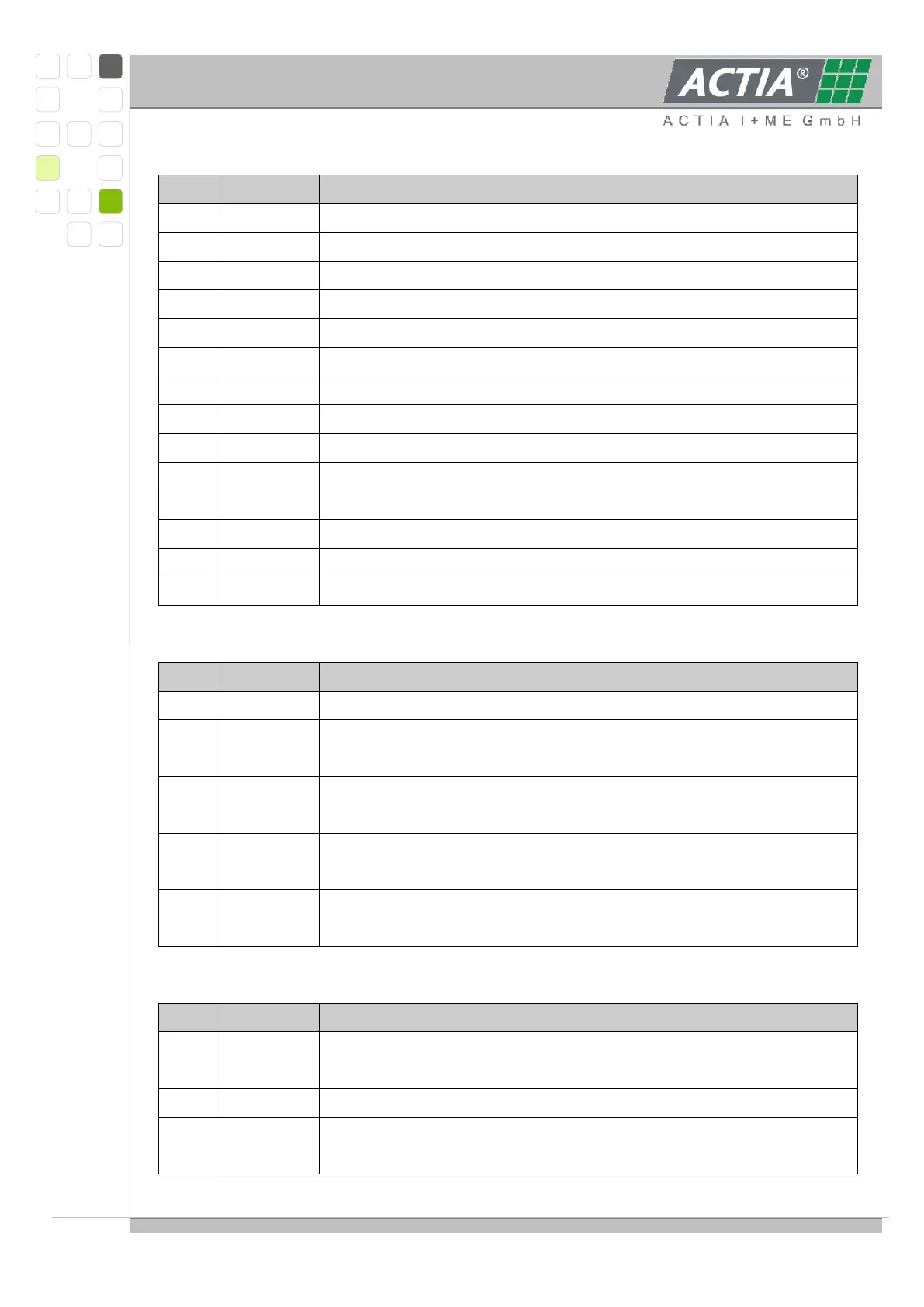
ANA module, 14 pole connector – cell voltage
Cell 1 Plus, Cell 2 Minus
Cell 2 Plus, Cell 3 Minus
Cell 3 Plus, Cell 4 Minus
Cell 4 Plus, Cell 5 Minus
Cell 5 Plus, Cell 6 Minus
Cell 6 Plus, Cell 7 Minus
Cell 7 Plus, Cell 8 Minus
Cell 8 Plus, Cell 9 Minus
Cell 9 Plus, Cell 10 Minus
Cell 10 Plus, Cell 11 Minus
Cell 11 Plus, Cell 12 Minus
ANA module, 10 pole connection - Temperature sensors
Do not use, detection over temperature balance board
NTC Temperature sensor 1, 10kOhm at 25°C
1. Sensor for measurement data
NTC Temperature sensor 2, 10kOhm at 25°C
2. Sensor for measurement data
NTC Temperature sensor 4, 10kOhm at 25°C
Second Level Protection, detection under temperature
NTC Temperature sensor 5, 10kOhm at 25°C
Second Level Protection, detection over temperature
ANA module, 8 pole connection Bottom – communication to previous module
Differentially ISO SPI signal to CON module or to the previous
ANA – module
Differentially stimulation signal from CON or previous ANA module
(ca. 10kHz)