Hardware Manual
BMS Master 4 / 4.5
Ref.: IR14417 A 15.01.2018 Page 29/76
of twisted pair cables is required. The shield is connected to the BMS Master only.
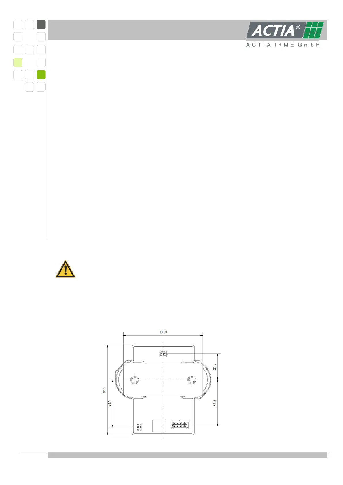
3.2.2.4 CONNECTING THE BAT-S 1000 1U SENSOR FOR VOLTAGE MEASUREMENT
For voltage measurement the 2-pole MicroFit-connector is used. The two pins are shorted
internally. The voltage measurement uses one side of the shunt as reference (see
3.2.2.1).
3.2.2.5 TECHNICAL SPECIFICATION BAT-S 1000 1U - SENSOR
Environmental Temp Range -40 / +85 °C
Current Meas. Range nominal ± 470 A
Current Meas. Range ext. ± 1200 A, max. 5 minutes
Offset ± 15 mA
Physical Resolution 15 mA nominal, 37 mA extended
Voltage Meas. Range nominal ± 1200 V
Physical Resolution 50 mV
Temperature Meas. Range -40 / +105 °C
Physical Resolution 0.1 °C
For further and detailed information on the BAT-S1000 1U refer to the product
specification by ACTIA I+ME GmbH.
The maximum current depends on the mechanical position and the heat dissipation
conditions. The high current cables connected provide a heat sink for the shunt. The
connections have to be made with a minimum contact resistance. The cable have to
be over dimensioned to achieve proper heat dissipation.
The inner heat resistance is approx. 2 K/W, the resistance is approx. 25µΩ and the
nominal power is approx. 15W. Ensure that under worst case operating conditions a shunt
temperature of 85 °C is not exceeded.