Hardware Manual
BMS Master 4 / 4.5
Ref.: IR14417 A 15.01.2018 Page 25/76
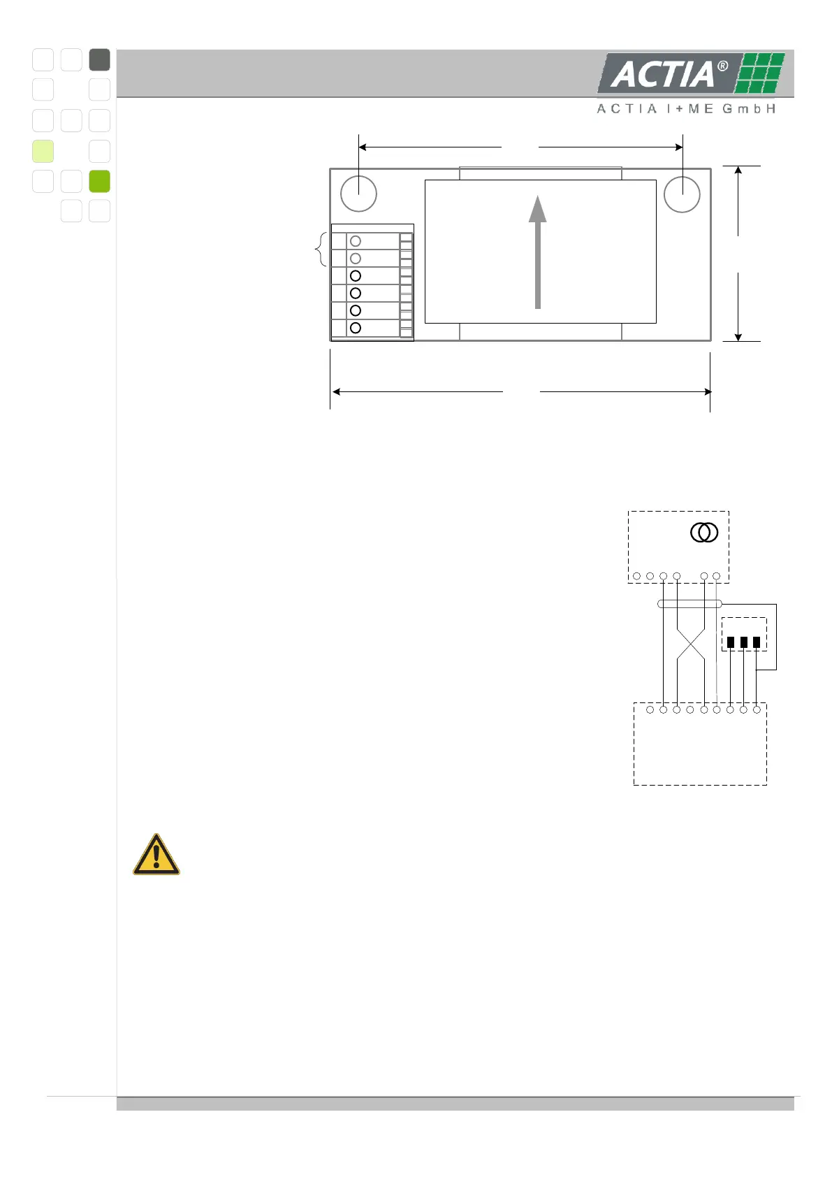
48.00
25.00
54.00
PTSA25-6
1
2
3
4
5
6
K2
K1
S2
S1
LC1
LC2
Compensation 2
Compensation 1
Sense 2
Sense 1
do not connect
3.2.1.1 CONNECTION TO THE MASTER
The picture shows the wiring between the
VAC_PCB board and connector
CN104 on BMS_MASTER.
Wire gauge must not exceed 0.5 mm² (AWG20).
Total wiring length should be kept as short as possible.
Current Direction:
The BMS measuring system interprets a negative current as a discharge current
and a positive one as a charge current. The load wiring has to be installed
accordingly.If necessary the measured current flow direction may be inverted by
interchanging the signal cables pairwise (K1 vs. K2 AND S1 vs. S2).Attention:
changing only one cable pair may result in sensor damage.
7V
1 2 3 4 5 6 7 8
S1
K1
KL31
S2
K2
CAN2H
CAN2L
Shield
9
Master04 - CN 104
CAN 2
LiYCY- TP 2x2 0,25mm²
K1 & K2 twisted
S1 & S2 twisted
Current sensor
VAC4645
K2
123456
K1
S2
S1
LC1
LC2