Hardware Manual
BMS Master 4 / 4.5
Ref.: IR14417 A 15.01.2018 Page 70/76
VBAT+
VBAT-
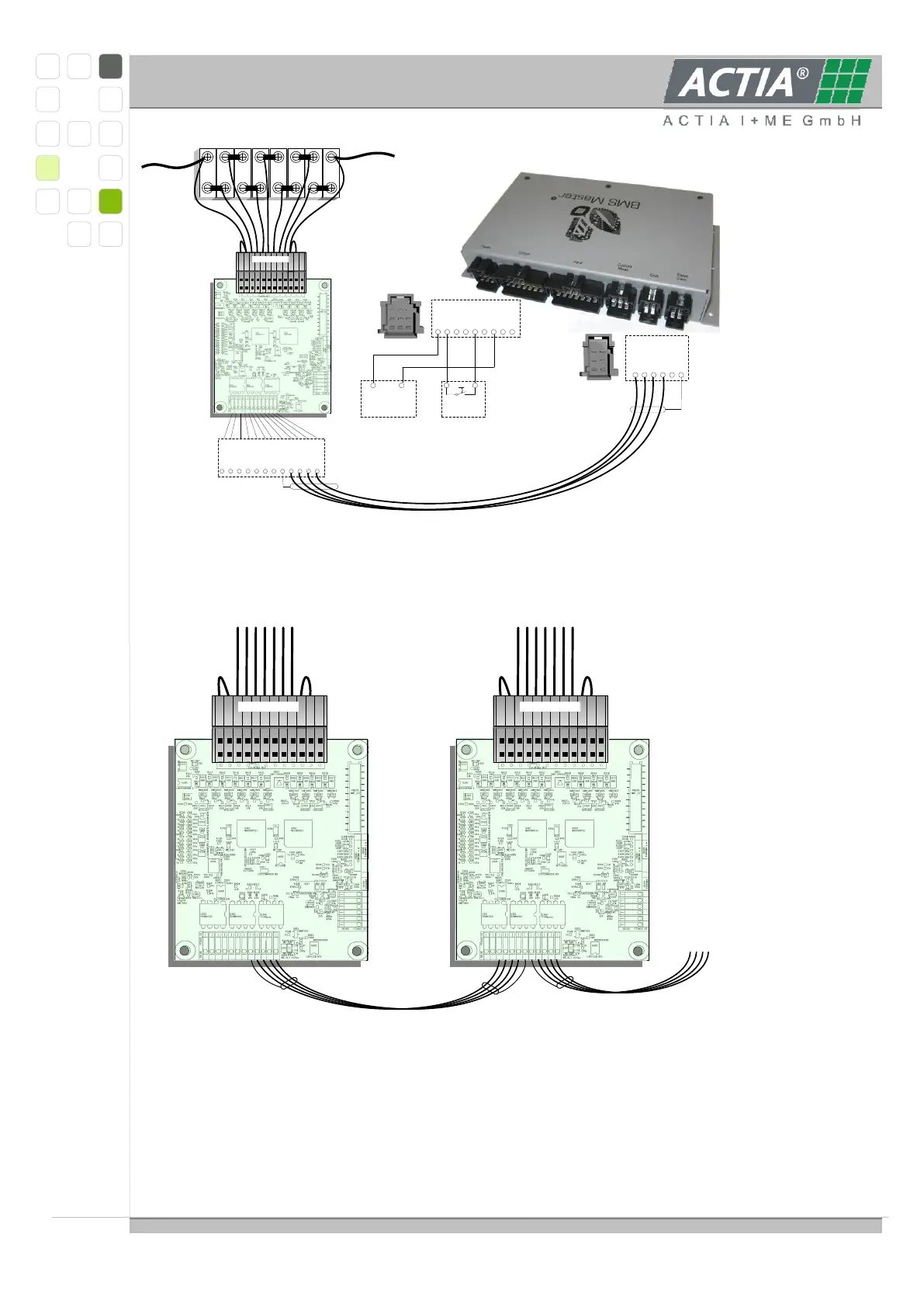
e.g. LiYCY- TP 3x2 0,25mm²
BUS A
BUS B
5V
GND
SHIELD
SHIELD
BUS A
BUS B
5V
GND
Failn 1
Failn 2
123456789101112
KL30
1 2 3 4 5 6 7 8
KL30
KL30
Plug In
Drive
EMSRET
KL31
KL31
KL31
9
Power
Power Supply
1 2
Vbat GND
1 2
Drive
BUS_A
1 2 3 4 5 6
5V NET
GND
BUS_B
FAIL_IN
Shield
Slave Com.
12 1
12 11 10 9 8 7 6 5 4 3 2 1
8-cell-wiring
Accordingly one Slave after the other has to be connected to the RS485 bus and be taken
in function. For the Slave_5 module this picture is valid analogously.
12 1
12 11 10 9 8 7 6 5 4 3 2 1
8-cell-wiring
12 1
12 11 10 9 8 7 6 5 4 3 2 1
8-cell-wiring
MASTER
Here can only be described how to bring the Slave modules in operation for the
measurement of the cell voltages which is the same in each application. We thought it
important to refer to the proper connection between Slave and battery that often showed
difficulties for some first users.
All starting ups happen in the responsibility of the system manufacturer.