SXG
48
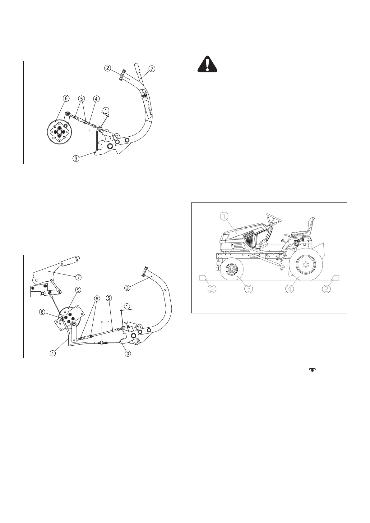
10. ADJUSTMENT OF BRAKE
(UE TYPE)
(1) clearance of spring coil (4) brake rod
(2) brake pedal (5) lock nut
(3) stopper (6) brake assy
a. Depress brake pedal(2) until it stops by stopper(3)
and adjust brake rod(4) so that clearance of spring
coil(1) is 0.6mm.
b. After adjusting brake rod(4), tighten the lock nut(5)
properly.
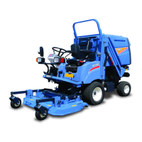
(UGE TYPE)
(1) clearance of spring coil (6) lock nut
(2) brake pedal (7) parking lever
(3) stopper (8) adjust cable nut
(4) brake cable (9) brake assy
(5) brake rod
a. Depress brake pedal(2) until it stops by stopper (3)
and adjust brake rod(5) so that clearance of spring
coil(1) is 0.3mm.
b. Pull up parking lever(7) until the 8 notch and adjust
the adjust cable nut(8) of brake cable(4) so that
clearance of spring coil(1) is 0.3mm.
c. After adjusting brake rod(5), tighten the lock nut (6)
properly.
11. NEUTRAL POSITION OF HST
Warning:
After a long time of use, the neutral position of the
HST unit can shift, which will cause various troubles
such as difficulty in stopping the lawn mower,
changing over between forward travel and reverse
travel, etc., which is very dangerous.
Important:
・ When the HST unit is out of order, ask your dealers to
repair it.
・ The adjustment of the neutral position of the HST unit
should be done by your dealers.
When there is no alternative but for the user to adjust it,
follow the next instructions: The neutral arm of the HST
unit is located around the centre under the step. With
this arm the neutral position can be adjusted.
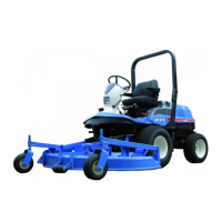
(1) Lawn mower (3) Front wheel
(2) Tyre chocks (4) Rear wheel
a. Place the lawn mower on level, hard ground Put tyre
chocks in the positions a little apart from the front
wheels and rear wheels as shown in the figure.
b. Shift the PTO lever to the OFF position (
).
c. Stop the engine and remove the starter key.
d. Apply the parking brakes (UGE) or locking brake (UE).
e. Loosen the lock nut of the adjust rod.
f. When the lawn mower creeps forward, tilt the adjust
nut slightly toward A and when creeps reverse, tilt
toward B by manipulating the adjust nut. Then tighten
it temporarily with the lock nut.