Operation and Application
c. Rotate the knob to select Ext In Edge and press [Enter] key to confirm.
d. Rotate the knob to switch Hi/Act and Lo/Act options. After selecting
Hi/Act or Lo/Act, press [Enter] key to confirm.
• Hi/Act: default value, indicating that the rising edge trigger is selected.
If the Pin 8 input signal is from 0V to 5V, the power output state
switches once.
• Lo/Act: indicate that the descending edge trigger is selected. If the
Pin 8 input signal is from 5V to 0V, the power output state switches
once.
e. Press [Esc] to exit the system menu setting.
3. There is an external DC voltage source capable of outputting 0V ~ 5V volt-
age between Pin 8 and Pin 24 of the DB25 interface to control power output.
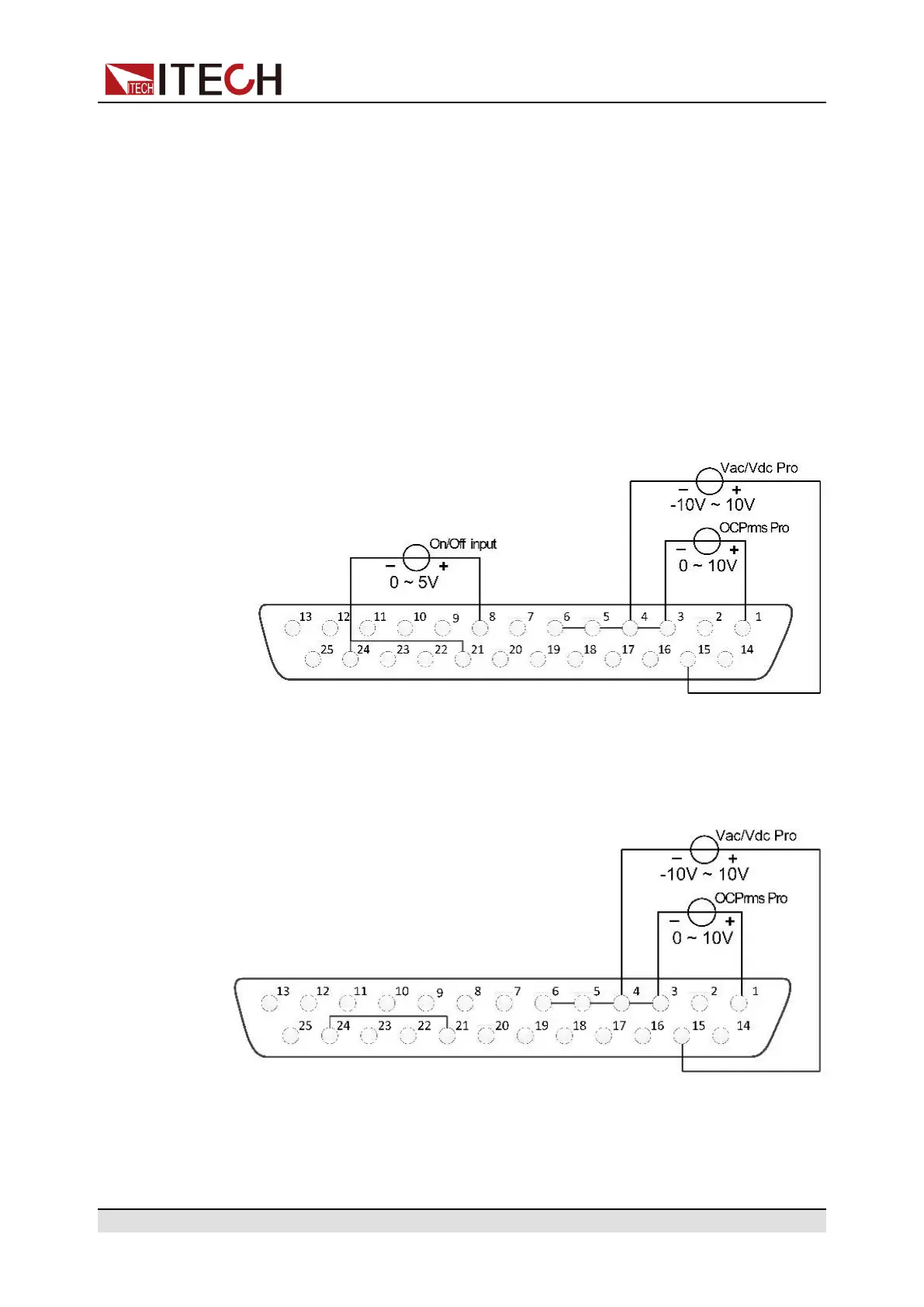
Analog Programming of Voltage and Current
This function can remotely change the voltage and current settings by sending
an external analog signal. The connection diagram is as follows:
• AC Mode
– Voltage setting: Analog control of the output voltage can be accom-
plished by connecting external DC voltage sources in the range of 0 V to
10 V to the 15 and 4 pins.
Copyright © Itech Electronic Co., Ltd.
91
 Loading...