EasyManuals Logo

ITT HYDROVAR Series User Manual

ITT HYDROVAR Series
100 pages
To Next Page IconTo Next Page
To Previous Page IconTo Previous Page
Page #28 background imageLoading...
Page #28 background image
27
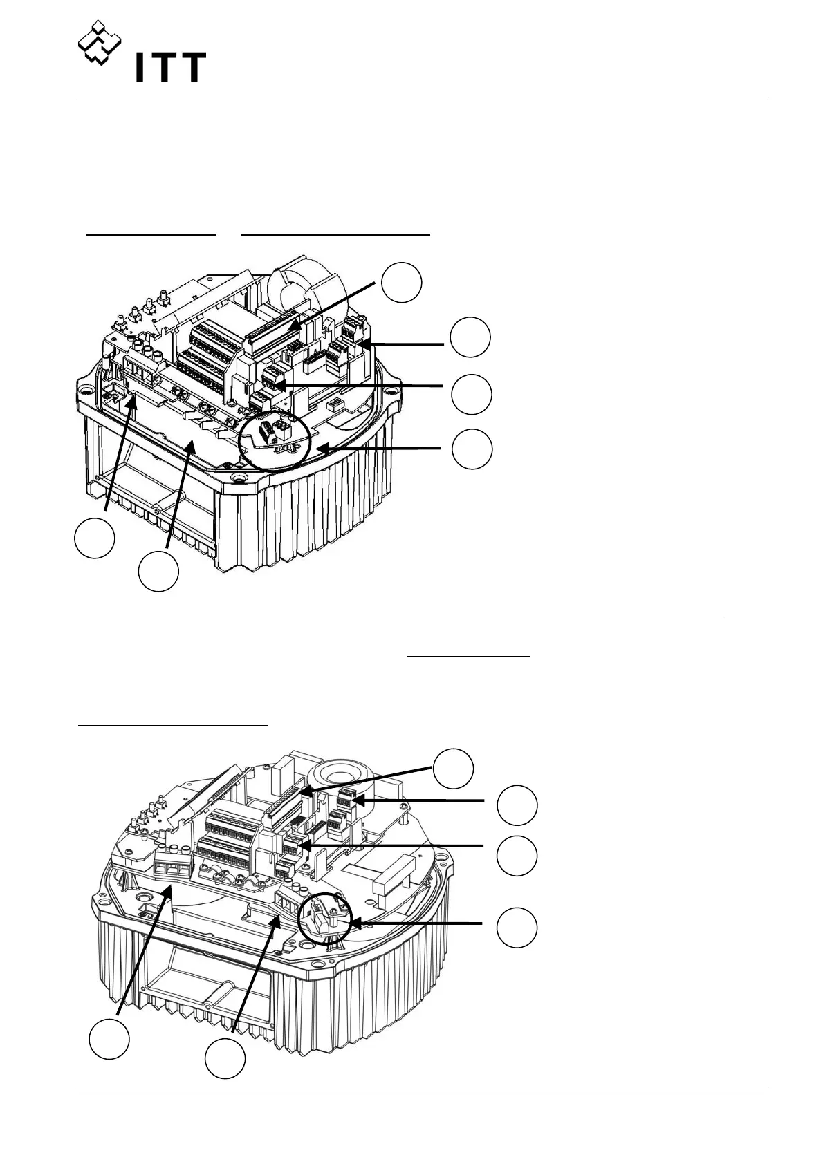
9.4 Wiring and connections
Remove the screws holding the top cover of the HYDROVAR.
Lift off the top cover. The following parts can be seen on a HYDROVAR Master / Single
Inverter:
HV 2.015 / 2.022 HV 4.022 / 4.033 / 4.040
(A) Power supply (D) Status-Relays (F) Terminal block:
- START/STOP
_
PTC
(B) Motor connections (E) RS-485 Interface - SOLORUN
- User Interface - RS-485 Interface
(C) Optional Relay Card - Internal Interface
HV 4.055 / 4.075 / 4.110
A
B
C
D
E
F
C
E
D
F
A
B

Questions and Answers:

Question and Answer IconNeed help?

Do you have a question about the ITT HYDROVAR Series and is the answer not in the manual?

ITT HYDROVAR Series Specifications

General IconGeneral
BrandITT
ModelHYDROVAR Series
CategoryControl Unit
LanguageEnglish

Related product manuals