35
9.4.4 Control Unit
Regarding the Hardware configuration of your HYDROVAR there are available two different
Control Cards.
The control unit of the HYDROVAR Master Inverter basically consists of the Control Card
and the additional boards which are connected to the Control Card via slot connectors. This
configuration is able to support all special software features and optional Boards.
The second available control card included in the HYDROVAR Single Inverter is developed
just for single pump operation. This control card also doesn’t support any additional
boards and includes just the minimum necessary software parameters.
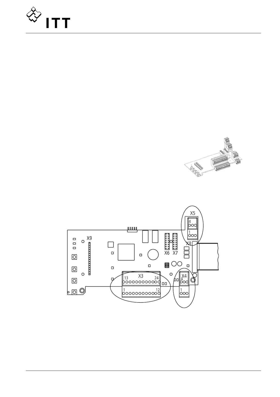
9.4.4.1 Control Card – HYDROVAR Master Inverter
The Control Card is connected to the power unit with a
ribbon cable on terminal X8.
• The display is connected to terminal X9
(the connection depends to the installation position).
• The connection terminals X6 and X7 can be used if optional boards are available.
e.g. The additional Relay Card can be connected to the Control Card at connection slot
X6.
X5- Status- Relays
X4- RS485 - Terminal
X3- Digital / Analogue
I /O
 Loading...