21
8 Mechanical Components
8.1 Included mounting material
Included
components
Cable gland Closing gland
Motor PTC
Mounting
clamps
Center-
piece
Terminals
for max.
[mm²]
M M M M M M
12 16 20 25 12 16
Cable
diameter
[mm]
3,5-7 4,5-10 7-13 9-17
2.015- 2.022 2 (3) 2 2 3 1 1 4 1 10
4.022- 4.040 2 (3) 2 2 3 1 1 4 1 10
4.055- 4.110 2 (3) 2 2 3 1 1 4 1 10
( ) max. available cable entries
8.2 Optional Components
8.2.1 Fittings
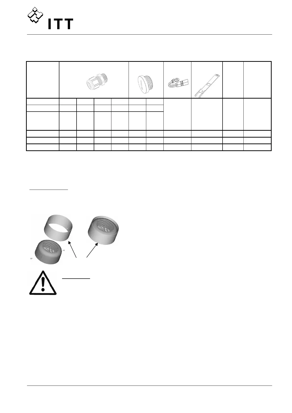
Mounting ring
Available for the diameters: 140 mm
155 mm
CAUTION!
If the HYDROVAR is mounted on a motor with plastic fan cover, a stainless-
steel mounting ring must be used.
8.2.2 Sensors
• pressure-transducer • temperature-sensor
• differential-pressure-transducer • flow indicator
• level-sensor
(orifice plate, inductive flow meter)
8.2.3 Filter
• Line-coils
8.2.4 Ready-made Motor cables
Available for HV 2.015 – 4.110
Mounting ring
 Loading...