73
0500
0500 SUBMENU
SEQUENCE CNTR.
Using the parameters in this submenu, all necessary settings can be done for running a
multi-pump system (even in Cascade Relay and Cascade Serial Mode).
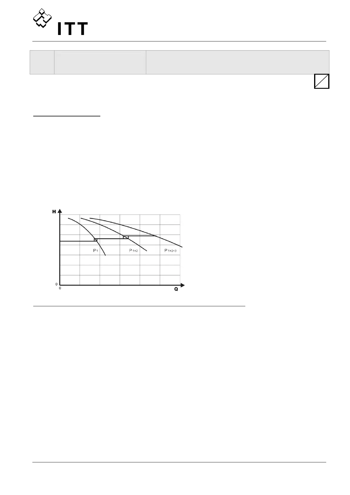
Application Example:
1) Lead pump reaches its ENABLE FREQUENCY [0515]
2) Actual value falls and reaches the cut in-value of the 1
st
follow up pump
Cut in-value = REQUIRED VALUE [02] – ACT. VAL. DEC. [0510]
Î the 1
st
follow up pump is switched on automatically
3) After the start up the new required value is calculated in the following way:
NEW REQUIRED VALUE = REQ.VAL.[02] – ACT.VAL.DEC[0510]. + ACT.VAL.INC.[0505]
The new required value is shown in the main menu as Parameter EFF.REQ.VAL.[03].
Calculation of the new required value for multi pump applications:
k ... Number of active pumps (k >1)
p = p
set
+ (k-1)*[lift value – fall value]
• Lift value = Fall value ⇒ Pressure constant even all pumps are in operation
• Lift value > Fall value ⇒ Pressure rises when lag-pump switches on
• Lift value < Fall value ⇒ Pressure falls when lag-pump switches on
S
 Loading...