46
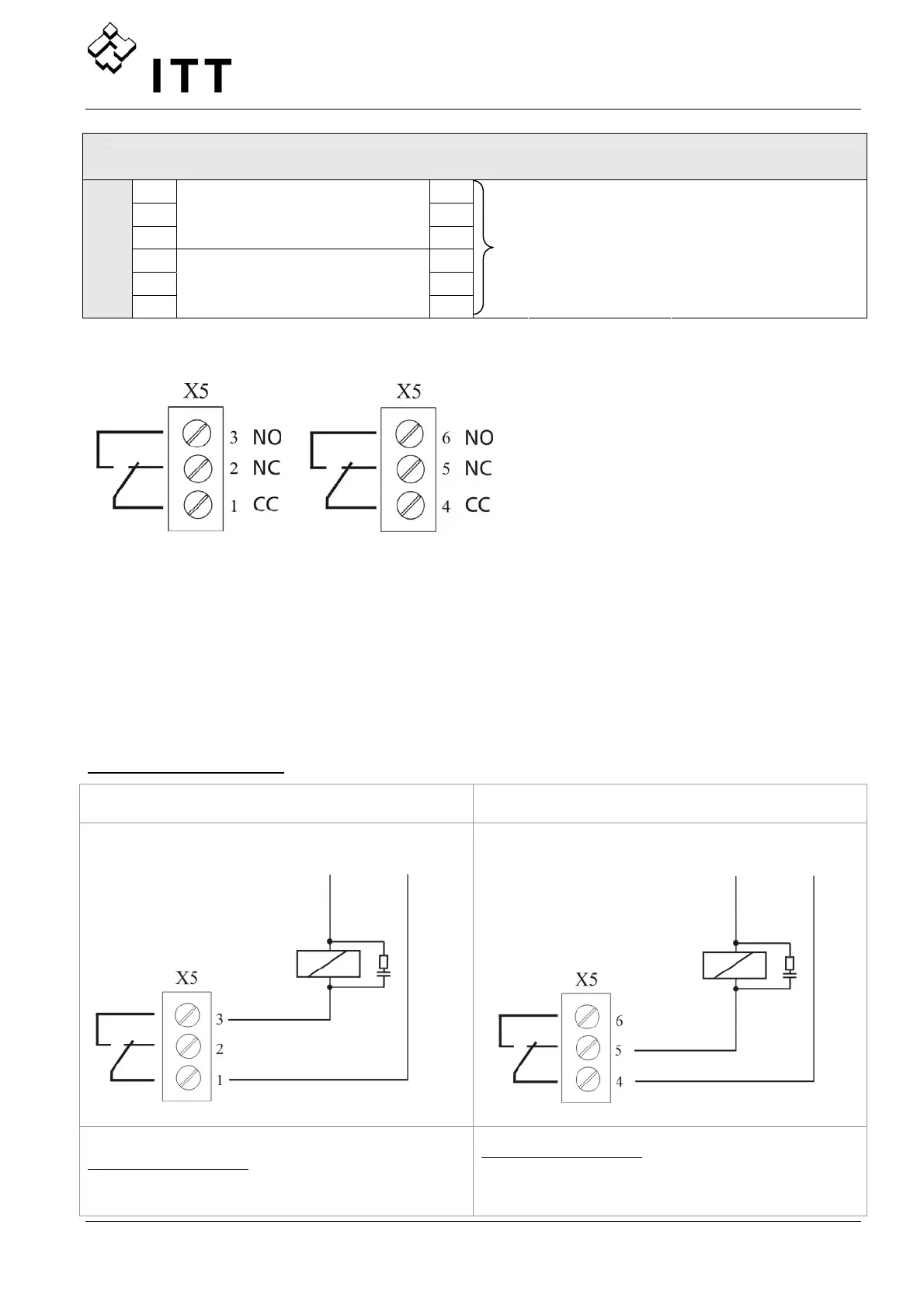
X5 Status-Relays
1
CC
2
NC
3
Status Relay 1
NO
4
CC
5
NC
X5/
6
Status Relay 2
NO
[Max. 250VAC]
[Max. 220VDC]
[Max. 30VDC]
[0,25A general use]
[0,25A general use]
[2A general use]
Status Relay 1 Status Relay 2
Please Note:
When using the relay contacts for
driving an external relay, a
corresponding RC-snubber-circuit is
recommended, to prevent disturbances
arising during a switching action of the
relay!
Both Status-Relays on the Control Card can be used regarding the programmed
configuration.
Depending to the programming, both relays can be used to indicate the current status and
failure messages of the HYDROVAR.
For example the two relays are used as Pump-running or Fault-signal-relay.
For this application see connection example below (How to program see Parameters CONF
REL 1 [0715] and CONF REL 2 [0720]).
Connection examples:
Pump running signal Fault signal
X5/ 1 and 3 closed:
- motor run indication
X5/ 4 and 5 closed:
- if there is a Fault/Error
- if the supply of the HYDROVAR is cut off
Ext. 250VAC
220VDC
Ext. 250VAC
220VDC
 Loading...