Page 9= Key 1 = Key 2 = Key 3 = Maximum or consumption = Minimum or supply
Product description
Intended use
The UMG 503 is suited for fix mounting and the measu-
rement of voltage, current, harmonics (2nd to 20th),
power etc. in low and medium voltage switchgear. For
the operation of the UMG 503 a protective wire is
required.
The measurement is laid out for one phase and three
phase systems with or without neutral conductor (three
wire measurement). If the measurement should be carried
out via two voltage transformers only, the option "three
wire measurement" is required.
Alternating voltages (50Hz/60Hz) up to 500VAC against
ground and 870VAC between the outer conductors can
be connected directly. The voltage measurement inputs
are not separated galvanicly and must be connected to
the UMG 503 via external prefuses M2A.
The current measurement is carried out via a ../5A or ../
1A current transformer. In networks with a voltage up to
150 VAC against ground currents up to 6 A can be
connected to the UMG 503 directly and measured as
well.
The connection of the auxiliary voltage, the measure-
ment inputs etc. are on the rear side via all-insulated plug
connectors.
The auxiliary voltage must be connected to the building
installation via a separation (switch or power switch) and
a 10 A overload protection.
Attention!
Measurement in systems with pulse load is not
possible, because no continuous scanning of the
measuring signals is carried out.
Functional description
The electronical three phase measurement system
determines and digitalizes the effective values of voltages
and currents in 50/60 Hz networks.
Two random test measurements are carried out each
second on all current and voltage measuring inputs.
Signal interruptions, which are longer than 500ms are
surely recognized. For each random test two periods are
scanned. From those sampled values the microprocessor
calculates the electrical magnitudes.
These measured values are indicated within the
programmable display.
Highest values, lowest values and programming data can
be saved in a battery buffered storage. Selected measu-
red values will be saved with date and time in a ring
buffer.
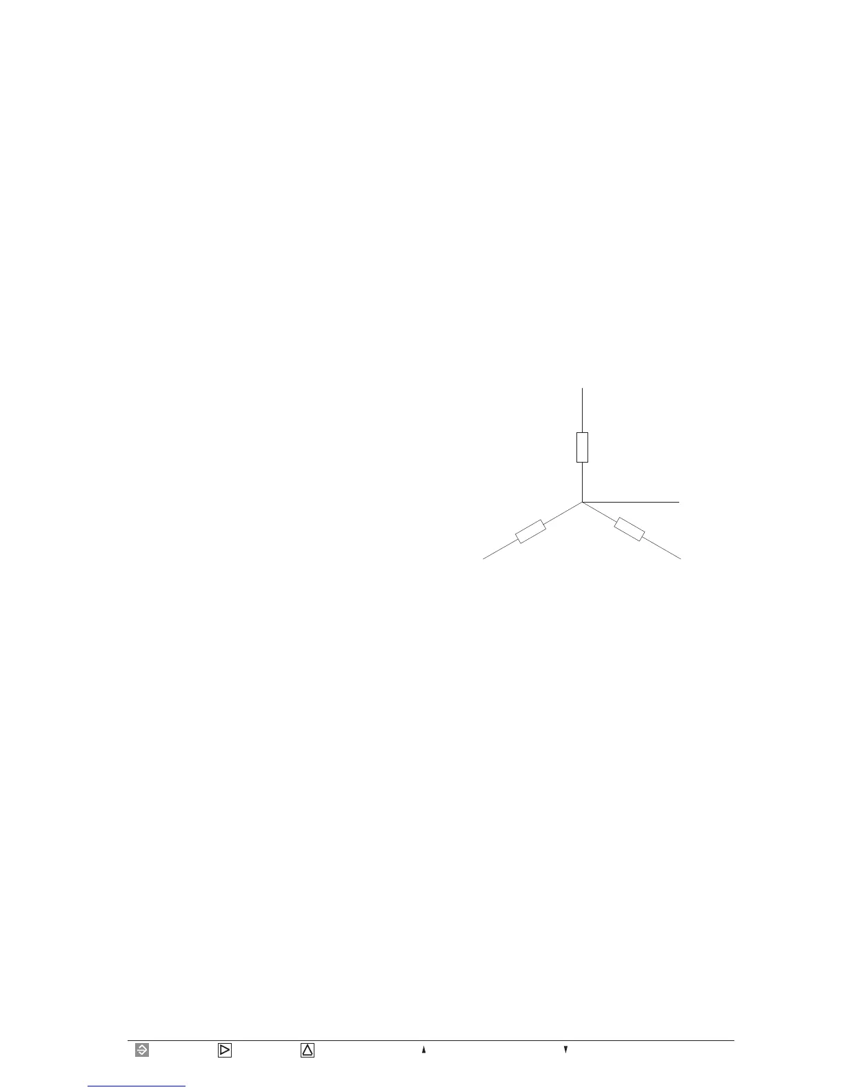
Diagr. Equivalent circuit diagram for voltage measurement
2 M
2 M
2 M
L1
L2
L3
PEN
 Loading...