P/N 960-100940R_Rev. A © 2016, JCM American Corporation
GEN5™ Series
Printer
Section 2
This section provides installation and preventive
maintenance procedures for the GEN5 Printer. This
section includes:
• Installation Procedure
• DIP Switch Configuration
• Connector Pin Assignments
• Preventive Maintenance
• Cleaning Procedure
Installation Procedure
Perform the following steps to install the GEN5
Printer Unit in the Host Machine:
1. Remove AC power from the Host Machine.
2. Identify the location where the
GEN5 Printer Unit
is to be installed.
3. Mount the Mounting Rail to the Host Machine
chassis using
a minimum of four (4) M4 x 4
screws or a mounting plate with four (4) M4 x 4
studs.
4. Slide the GEN5 Printer onto the Mounting Rail.
5. Connect the Power and Signal Connector to the
GEN5 Pri
nter Unit.
6. Restore AC power to the Host Machine.
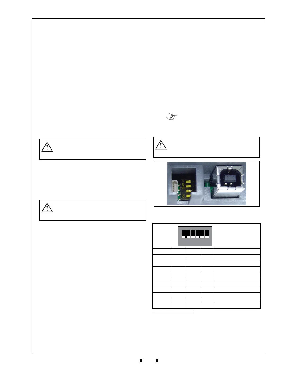
DIP Switch Configuration
This section provides the DIP Switch Configuration
Settings for SW1 through SW4 on the GEN5
Printer Unit (Figure 2-1). While Baud Rate settings
are auto-configured by the system’s firmware, auto-
configuration can be overridden by manually set-
ting the DIP Switches to configure baud rate set-
tings on the Printer Unit.
WARNING: Before performing this
procedure, observe the ESD WARNING
in “User Cautions” on page 1-2.
WARNING: The GEN5 Printer Unit
MUST be mounted to a grounded metal
plate.
Table 2-1 DIP Switch Baud Settings
*
*. DIP Switches SW5 and SW6 are NOT USED.
SW1 SW2 SW3 SW4
Mode (bps
†
)
†. bps = bits per second.
ON ON ON X 9600
ON ON OFF X 9600
ON OFF ON X 19200
OFF ON OFF X 38400 (Default)
OFF ON ON X 57600
OFF OFF OFF X 115200
OFF OFF ON X 307200
ON OFF OFF X 921600
X X X OFF XON/XOFF (SW)
XXXON RTS
NOTE: Baud Rate settings are auto-
configured by the system’s firmware.
Baud settings in Table 2-1 are
provided for reference.
WARNING: DIP Switches SW5 and SW6
are reserved - DO NOT change the
settings on these DIP Switches.
Figure 2-1 DIP Switch and Firmware Update Port
 Loading...