P/N 960-100940R_Rev. A © 2016, JCM American Corporation
Section 4 GEN5™ Series Printer Disassembly/Reassembly
Print Mechanism Disassembly
The Print Mechanism includes the TOF Sensor and
Upper Presenter Motor. To disassemble it, proceed
as follows:
1. Carefully cut and remove tie wraps, as needed.
2. Remove the e-clip on the Hinge Pin (Figure 4-4
a).
3. Pull the Hinge Pin (Figure 4-4 b) out of the side
of t
he Print Head, separating the Mounting
Bracket from the Lid
Assembly.
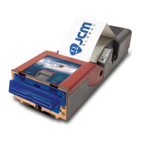
4. Remove four (4) screws securing the Print Head
(Figure 4-4 c
1
thru c
4
).
5. Remove the Print Head (Figure 4-4 d) from the
Lid Assemb
ly.
TOF Sensor Removal
To remove the TOF Sensor:
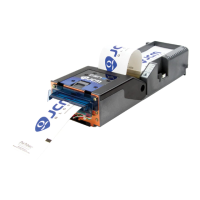
1. Remove the two (2) screws (Figure 4-5 a
1
& a
2
)
securing the right side cover (Figure 4-5 b) to the
Prin
t Mechanism. Then remove the right side
cover.
2. Move the Harness out of the Guides (Figure 4-6
a).
3. Remove the Plastic Pin using a flat-edge screw-
driver (Figure 4-6 b).
4. Carefully slide the TOF Sensor board out of the
Print Head (Figu
re 4-6 c).
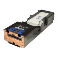
Figure 4-3 Remove Upper Presenter
Figure 4-4 Print Head Removal
Figure 4-5 Right Side Cover Removal
NOTE: Be sure to save the End Caps
that hold the TOF Sensor in place.
Figure 4-6 TOF Sensor Removal
 Loading...