P/N 960-100940R_Rev. A © 2016, JCM American Corporation
Installation GEN5™ Series Printer Section 2
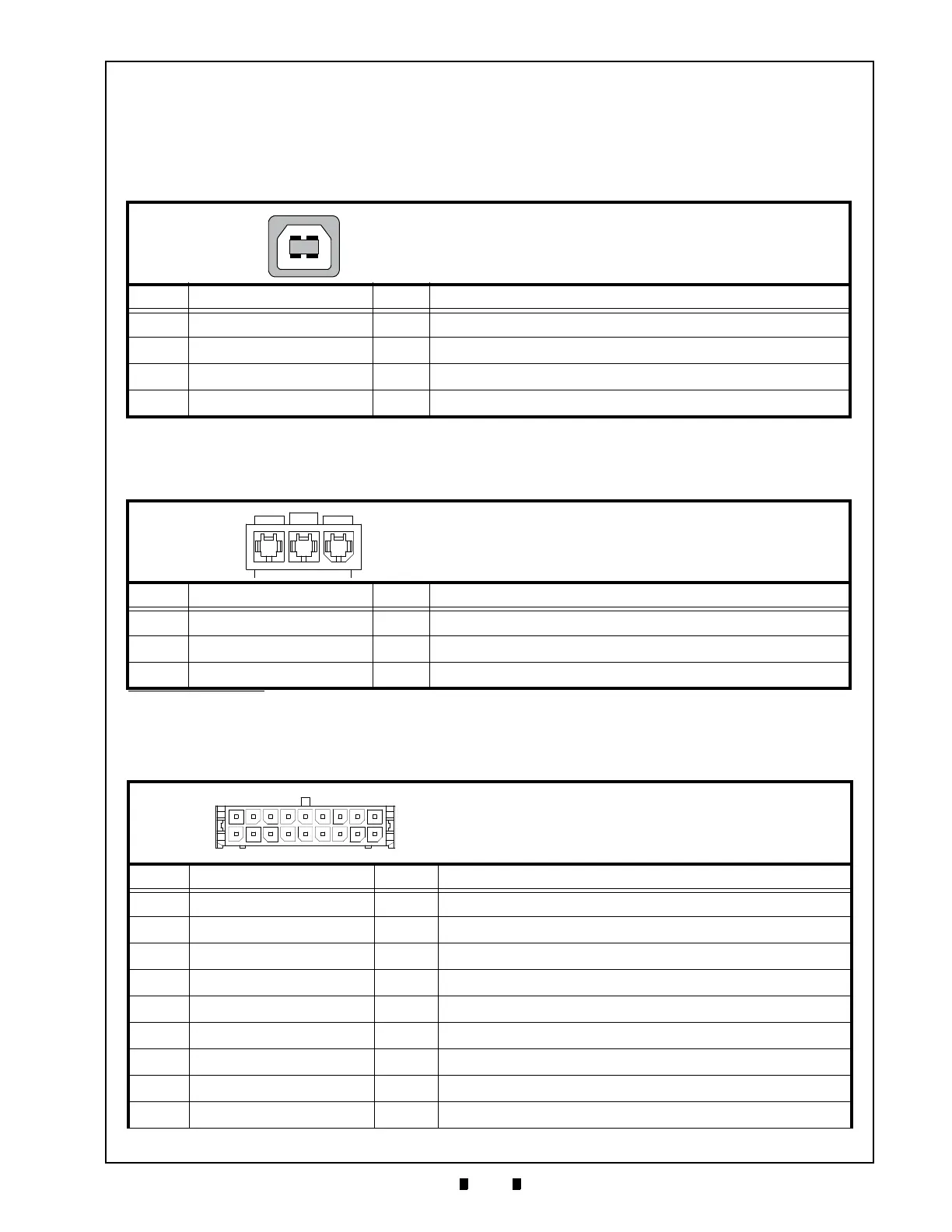
Base Port Connector Pin Assignments
Table 2-4 lists the GEN5 Base Port Connector Pin Assignments.
Table 2-4 GEN5 Base Port Connector Pin Assignments
Pin No. Signal Name I/O Function
1 DGND - Ground
2 USB- I/O USB- (N)
3 +13V - No Connection
4 Switched+24V - Switched 24V Bezel
5 DTR - Data Terminal Ready
6 MRESET - Master Reset
7 USB+ I/O USB+ (P)
8 +24V DC - +24V DC Power Supply
9 RTS - Request to Send
Connector Pin Assignments
Table 2-2 through Table 2-8 list the GEN5 Printer Unit’s pin assignments.
Firmware Update Connector Pin Assignments
Table 2-2 lists the GEN5 Firmware Update Connector Pin Assignments.
Bezel LED Connector Pin Assignments
Table 2-3 lists the GEN5 Bezel LED Connector Pin Assignments.
Table 2-2 GEN5 Firmware Update Connector Pin Assignments
Pin No. Signal Name I/O Function
1 VCC (+5V) - +5V DC Power Supply
2 DATA - I/O USB Communication Input/Output Signal Line
3 DATA+ I/O USB Communication Input/Output Signal Line
4 GND - Signal Ground
Table 2-3 GEN5 Bezel LED Connector Pin Assignments
*
*. Bezel Connection on face of the GEN5 Printer Unit.
Pin No. Signal Name I/O Function
1 Power 24V O Switched 24V 100mA Min
2
BGND
-
Bezel Ground
3
Frame Ground
-
Frame Ground
Power Source: USB B Plug
Connector: 6717101-000 (MOLEX)
Connector: 43640-0301 (Micro-Fit)
Mate: 43645-0300 (Micro-Fit)
Connector: 43025-1800 (MOLEX)
Mate: 43045-1812 (MOLEX)
Coil Interface Connector/RS232C/USB
 Loading...